VÅNTEC-1 Detector User Manual Hardware Installation for the D8 ADVANCE
M88-E01072 4 - 13
4.7.2 Connection and Cable Wiring
The cabling differs in one way compared to that
in Figure 4.6:
1. The motor clock cable (A17-D42) has to be
connected between the 9-pin socket STEP/
DIR of the Detector Controller or external
FDC and either:
•For D8 systems, the X5 9-pin socket on the
B231 2-axis indexer board, or
•For D4 systems, the socket on the bracket
(X11) of the B232 4-axis indexer board.
NOTE: The clock signal cable can be one of two
cables, one straight and one Y-shaped. If you
are running the system with the AIB2G, NEVER
use the Y-shaped adapter cable (A17-D43) in
any case!
After connecting the cables, switch on the
detector controller and D8/D4 system.
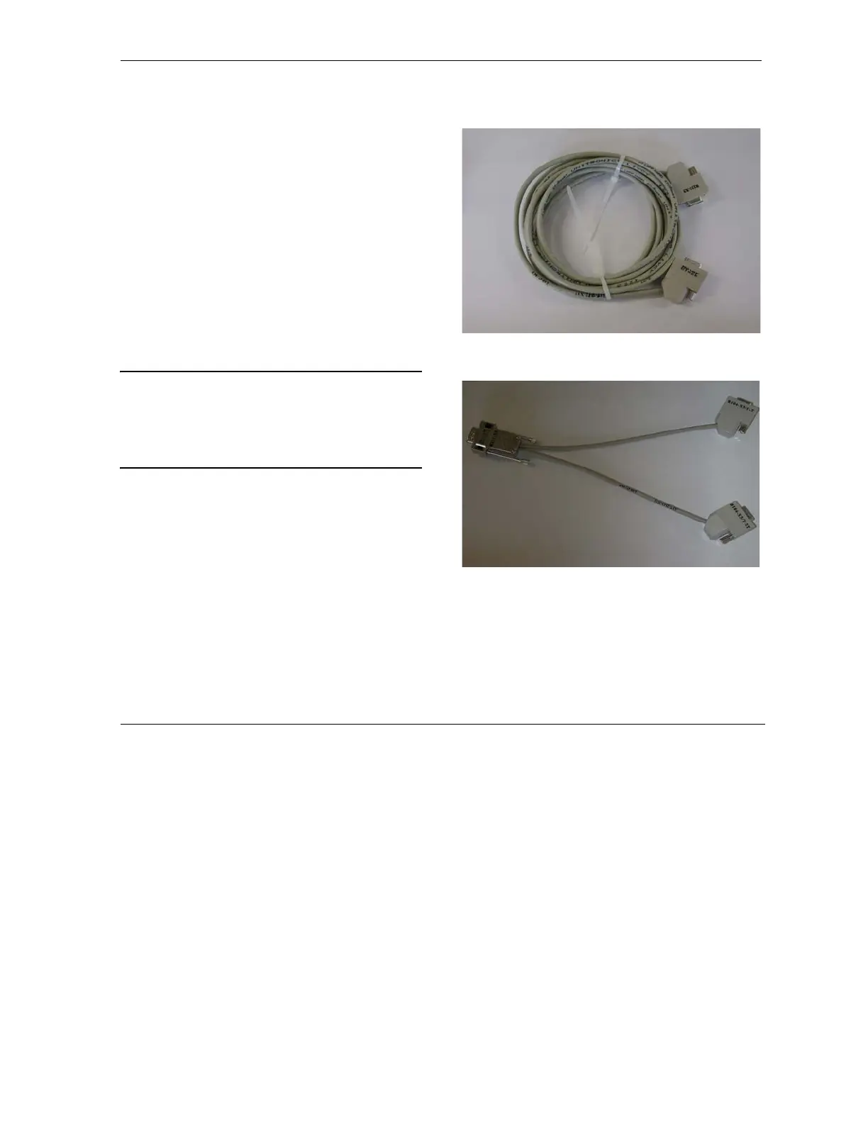
Figure 4.8 - Clock signal cable (A17-D42)
Figure 4.9 - Y-shaped adapter cable (A17-D43).
NOTE: Use only for first-generation indexer
boards (AIB) B104/B105.