VÅNTEC-1 Detector User Manual Hardware Installation for the D4 ENDEAVOR
M88-E01072 5 - 3
5.4 Hardware Installation
Use the following tools for this procedure:
• Loctite 422
• Torx screwdriver
• Allen screwdriver
Additional rails and hardware must be mounted
to accommodate the VÅNTEC-1 controller and
FDC (if present) in the D4. The location of the
FDC (if present) and PSD controllers is critical
for proper operation. There must be sufficient
airflow around the controllers to prevent the
electronics from overheating. Do not place the
VÅNTEC-1 controller in close proximity to the
generator. This may induce electronic noise in
the detector electronics.
Use care when moving the detector head to
avoid mechanical shock to the assembly.
See Table A.3 in Appendix A for the configura-
tion scheme.
5.4.1 Mount the Rails and Detector
1. Remove the D4’s left side panel.
2. Remove the rack for the electronics.
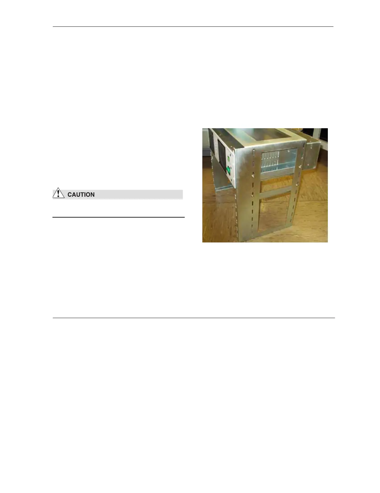
3. Mount the rails and attach the rack nuts at
the positions shown in Figure 5.1. The FDC
(if present) must be mounted below the
detector controller. Otherwise, the airflow
inside the detector controller is restricted.
Figure 5.1 - Mount the controllers in the electronics rack
4. Adjust the height of the rails so that the con-
troller can be fixed to the rack nuts.
5. Take out the controllers and mount the rack
into the system again.
 Loading...