Hardware Installation for the D4 ENDEAVOR VÅNTEC-1 Detector User Manual
5 - 6 M88-E01072
9. To mount the detector, use M5 30 mm Torx
screws and place the detector onto the
goniometer. Use the same position as used
with the secondary slit system with the scin-
tillation counter (see Figure 5.10).
Position additional components, such as the
scintillation counter and slit systems, so that no
cables or components can collide or jam with
the sample lift.
5.4.2 Install the Primary Beam Stop
1. Remove the cover of the sample magazine
and all side and back panels.
2. Mount the special handles for the front
panel. Turn the safety key to position 1.
Open the front panel.
3. Remove the scintillation counter, propor-
tional counter (Ca channel) or SOL-X detec-
tor and position the components so that
they will not collide with other components.
4. Using Service Support mode, drive the sam-
ple lift to 200 mm.
5. Using Service Support mode, drive the
detector to 100° 2-theta and the sample
holder to 70° theta.
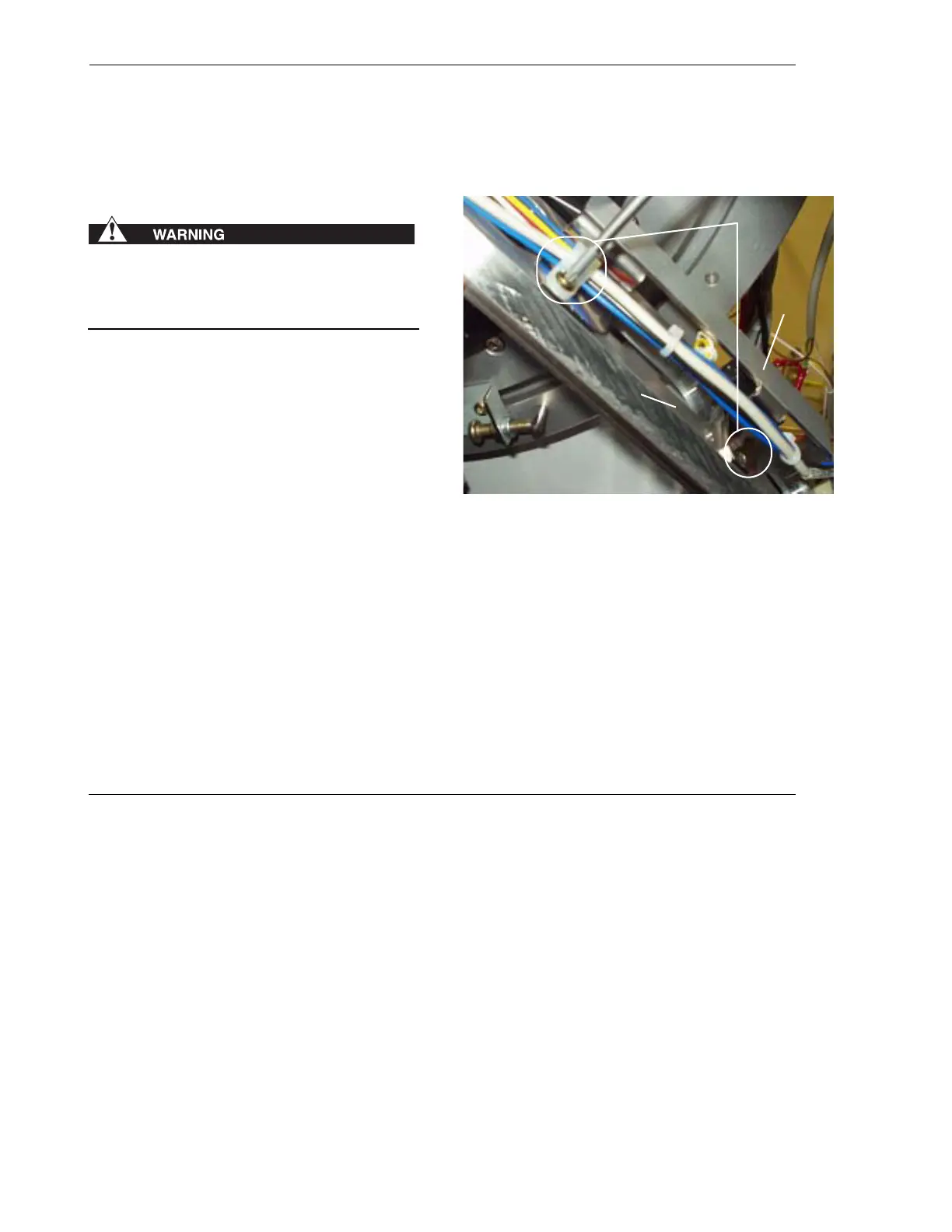
6. Mount the bracket for the magnet of the
beam stop. Secure the slide for the beam
stop using the screws and cable clamps as
shown in Figure 5.7.
Figure 5.7 - Mount the bracket for the magnet of the
beam stop
Bracket for
magnet
Sample
lift
Screws and
clamps