VÅNTEC-1 Detector User Manual Hardware Installation for the D4 ENDEAVOR
M88-E01072 5 - 7
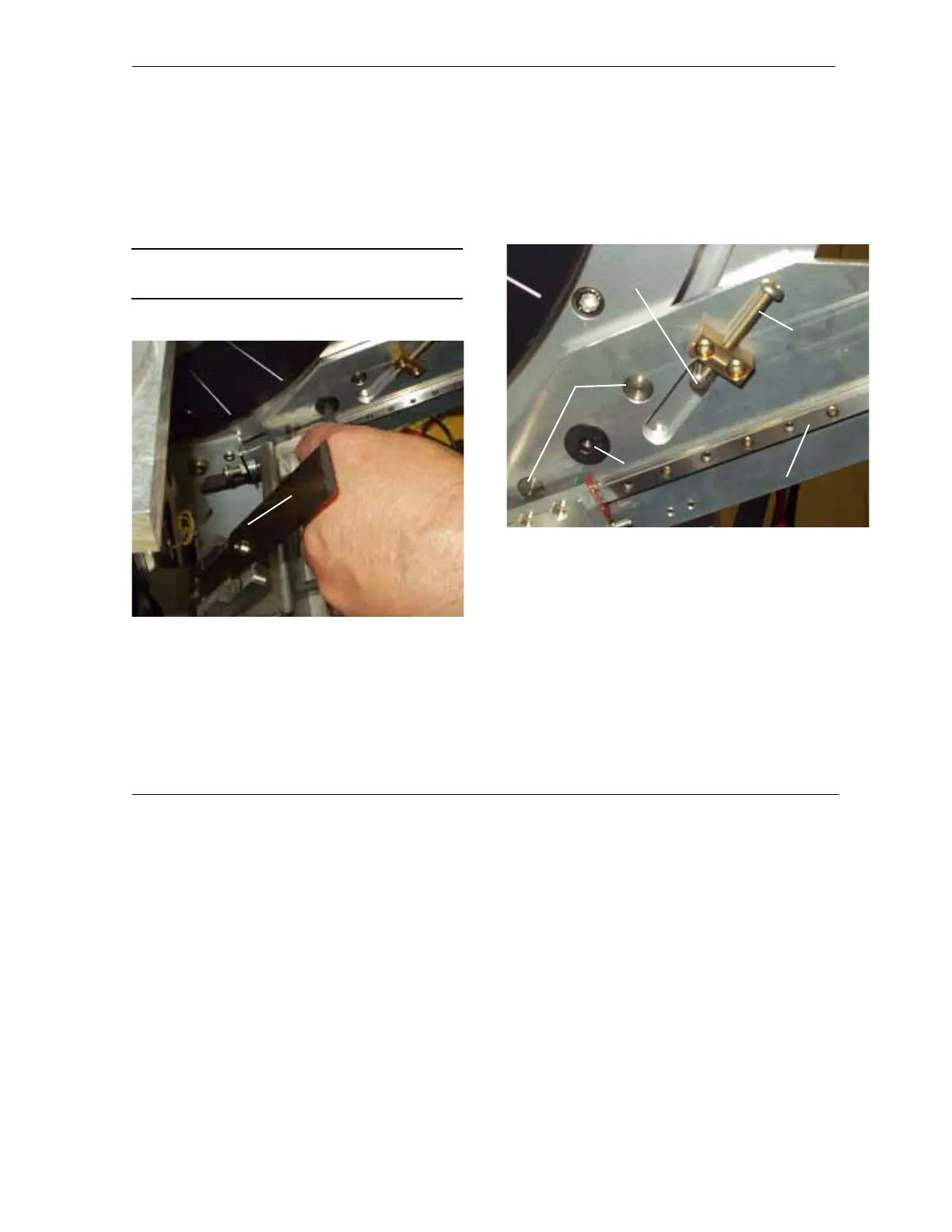
7. Drive the sample holder to 30° and mount
the beam stop for the D4 (see Figure 5.8).
Place a T-nut into the groove ring of the
goniometer and tighten the fixing screw.
Ensure that the two additional pins also fit
into the groove ring.
NOTE: Do not lose the T-nut in the groove—put
a tissue into the groove to prevent this.
Figure 5.8 - Mount the primary beam stop
8. Screw the alignment screw completely out
(see Figure 5.9). Put the alignment pin into
the goniometer ring and place the beam
stop so the alignment screw hits the align-
ment pin.
Figure 5.9 - Details of the primary beam stop—showing the
extreme low position of the beam stop
Primary
beam
stop
Alignment
screw
Linear
guidance
Alignment
pin
Fixing
screw
Positioning
pins