Hardware Installation for the D4 ENDEAVOR VÅNTEC-1 Detector User Manual
5 - 8 M88-E01072
9. Mount the actuator for the beam stop colli-
sion switch using a T-nut in the groove ring
(see Figure 5.10). The position of the actua-
tor is defined by the extreme low position of
the alignment screw and shows the highest
position of the primary beam stop (about 6°
2-theta).
Figure 5.9 shows the actuator in the
extreme high position of the alignment
screw.
Figure 5.10 - Mounting of the actuator bracket for beam stop
collision switch
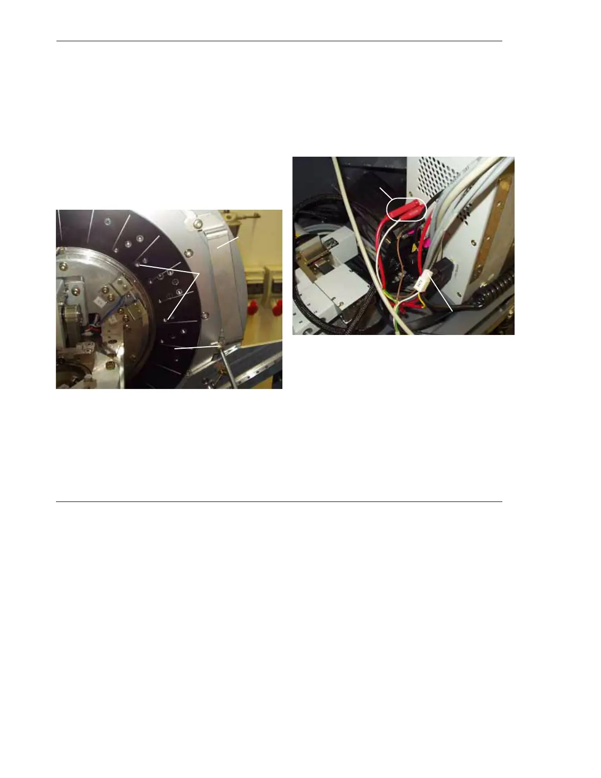
10. Mount the collision switch to the detector
mount. Place the color-coded banana plugs
into the sockets on the goniometer side
panel labeled “Collision switch.” Do not
switch the colored plugs and sockets (see
Figure 5.11).
Figure 5.11 - Cabling of the collision switch
11. Connect the plug X672 to the cable for the
switch monitoring in D4TOOLS.
Actuator/
bracket
Mount
positions
Fixing of
actuator
Plugs of
collision
switch
Connector for the
switch monitor