VÅNTEC-1 Detector User Manual Hardware Installation for the D8 ADVANCE
M88-E01072 4 - 9
4.5.2 Connections and Cable Wiring
The latest version of the VÅNTEC-1 runs with
an integrated FDC located inside the detector
controller. Cabling (see Figure 4.6) differs in 2
ways compared with Figure 4.3:
1. The serial cables, used for measuring and
service, are connected directly between the
COM ports of the detector controller and the
D8 Electronics Rack. COM1 is for Measur-
ing, COM2 is for Service.
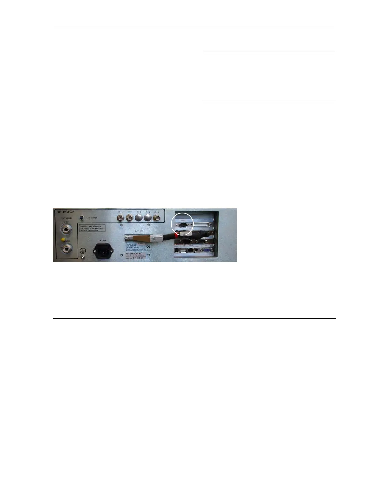
2. The motor clock cable (A17-D42) must be
connected between the 9-pin STEP/DIR
port on the rear of the detector controller
(see Figure 4.5) and either:
•For D8 systems, the X5 9-pin port on the
B104 2-axis indexer board, or
•For D4 systems, the socket on the bracket
of the B105 4-axis indexer board.
Important: When replacing the clock signal
cable for an external FDC, there is an additional
adapter with two 9-pin plugs labeled either:
“T-T” for D8 Theta-Theta goniometer, or
“T-2T” for D4 or D8 Theta-2Theta goniometer
(A17-D43).
After connecting the cables, switch on the
detector controller and D8/D4 system.
Figure 4.5 - Back panel of the VÅNTEC-1 detector
controller. The circle shows the connection
STEP/DIR for the motor clock signal.
STEP/DIR