VÅNTEC-1 Detector User Manual Hardware Installation for the D8 ADVANCE
M88-E01072 4 - 19
4.7.7 Manual Installation for Theta-2Theta
Configuration
In 21 CFR Part 11 situations, manual setup is
mandatory. Otherwise, the use of automated
installation for the Clock Signal is recommended
(see Section 4.7.5).
1. Make sure that the Automatic Drive Config-
uration is disabled by unchecking the check-
box in Figure 4.12.
2. Select Advanced Board Setup > Two Axis
Indexer Boards. Ensure that physical drive
1 is connected to logical axis THETA, and
physical drive 2 is connected to logical axis
2THETA (see Figure 4.17).
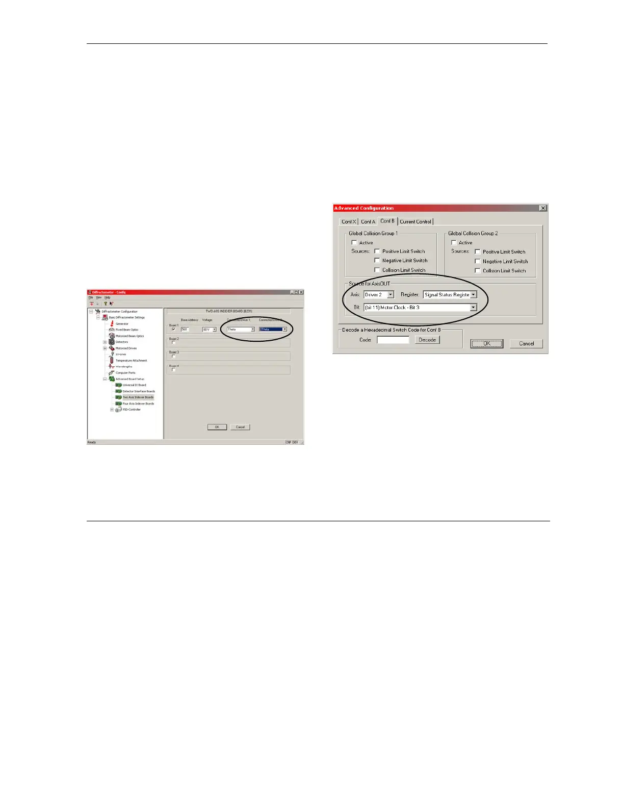
Figure 4.17 - Advanced Board Settings – Two Axis Indexer
Board. Settings for Theta-2Theta.
3. Select Motorized Drives > Theta. Click
Change Values.
4. Answer Yes to the confirmation message
and click Additional Settings. The follow-
ing box appears (see Figure 4.18). The
“Axis” must be set to Driver 2. Set “Regis-
ter” to Signal Status Register and “Bit” to
(bit 11) Motor Clock - Bit 3.
Figure 4.18 - Motorized Drives section – Theta – Advanced
Configuration