Hardware Installation for the D8 ADVANCE VÅNTEC-1 Detector User Manual
4 - 18 M88-E01072
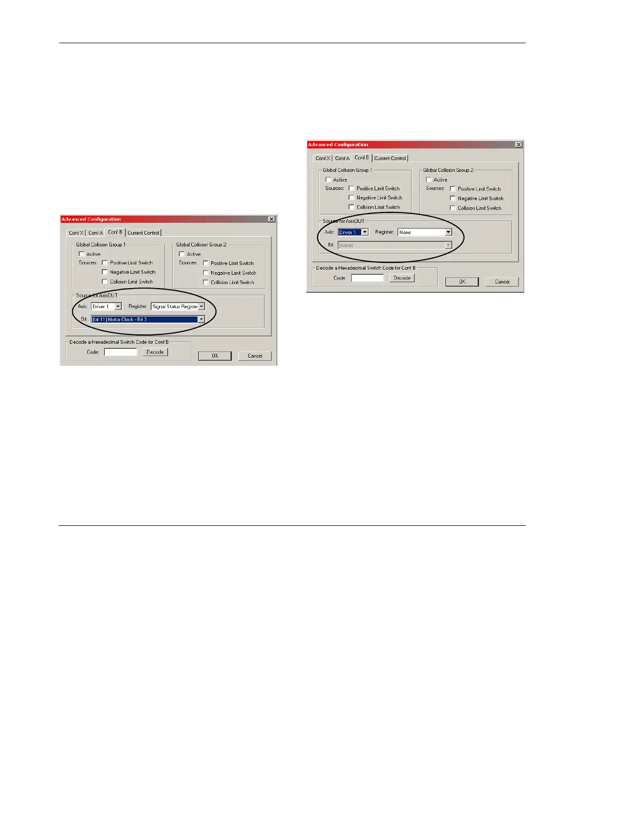
4. Answer Yes to the confirmation message
and click Additional Settings. The follow-
ing box appears (Figure 4.15). Select the
axis that should deliver the Clock signal.
Because the logical axis TH-Detector is
sending the clock signals, this motor axis
has to be chosen. From Figure 4.13, the
“Axis” must be Driver 1. Set “Register” to
Signal Status Register and “Bit” to (bit 11)
Motor Clock - Bit 3.
Figure 4.15 - Motorized Drives section – TH-Detector –
Advanced Configuration
5. Also check the settings of the logical axis
TH-Tube in the same way. The parameters
for “Sources for AxisOUT” must look like
Figure 4.16.
Figure 4.16 - Motorized Drives section – TH-Tube –
Advanced Configuration
6. Save and download the configuration.