Hardware Installation for the D8 ADVANCE VÅNTEC-1 Detector User Manual
4 - 14 M88-E01072
4.7.3 Hardware Installation
Configure the VÅNTEC-1 detector as shown in
Figure 4.6. Connect the AIB2G to the system.
NOTE: Power down the complete D8 system
before changing circuit boards on the D8
Controller Rack. Changing boards in the D8
Controller Rack without powering down the
system can damage both the boards and the
Controller Rack.
NOTE: Never mix old and new Axis Indexer
Boards! The boards may be rendered
inoperable as a result.
When using the B104 or B105 Axis Indexer
Boards, connect the motor clock cable and
indexer cables as described in Section 4.5.2.
When using the 2-axis version of the AIB2G
(B231), the motor clock cable must be attached
to X5.
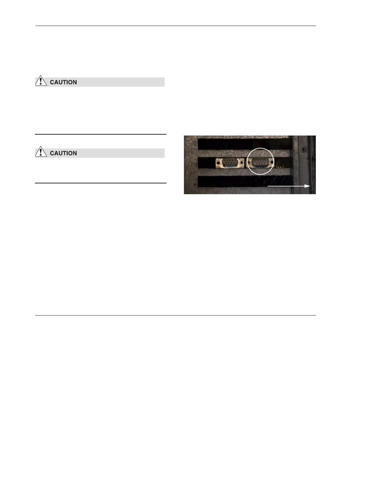
When using the 4-axis version of the AIB2G
(B232), the motor clock cable must be attached
to X11. The connection X11 is located on the
bracket of the board (see Figure 4.10).
Figure 4.10 - Top view of the 4-axis AIB2G (B232). The X11
socket is used for the Motor Clock Signal.
X11
front