VÅNTEC-1 Detector User Manual Hardware Installation for the D4 ENDEAVOR
M88-E01072 5 - 9
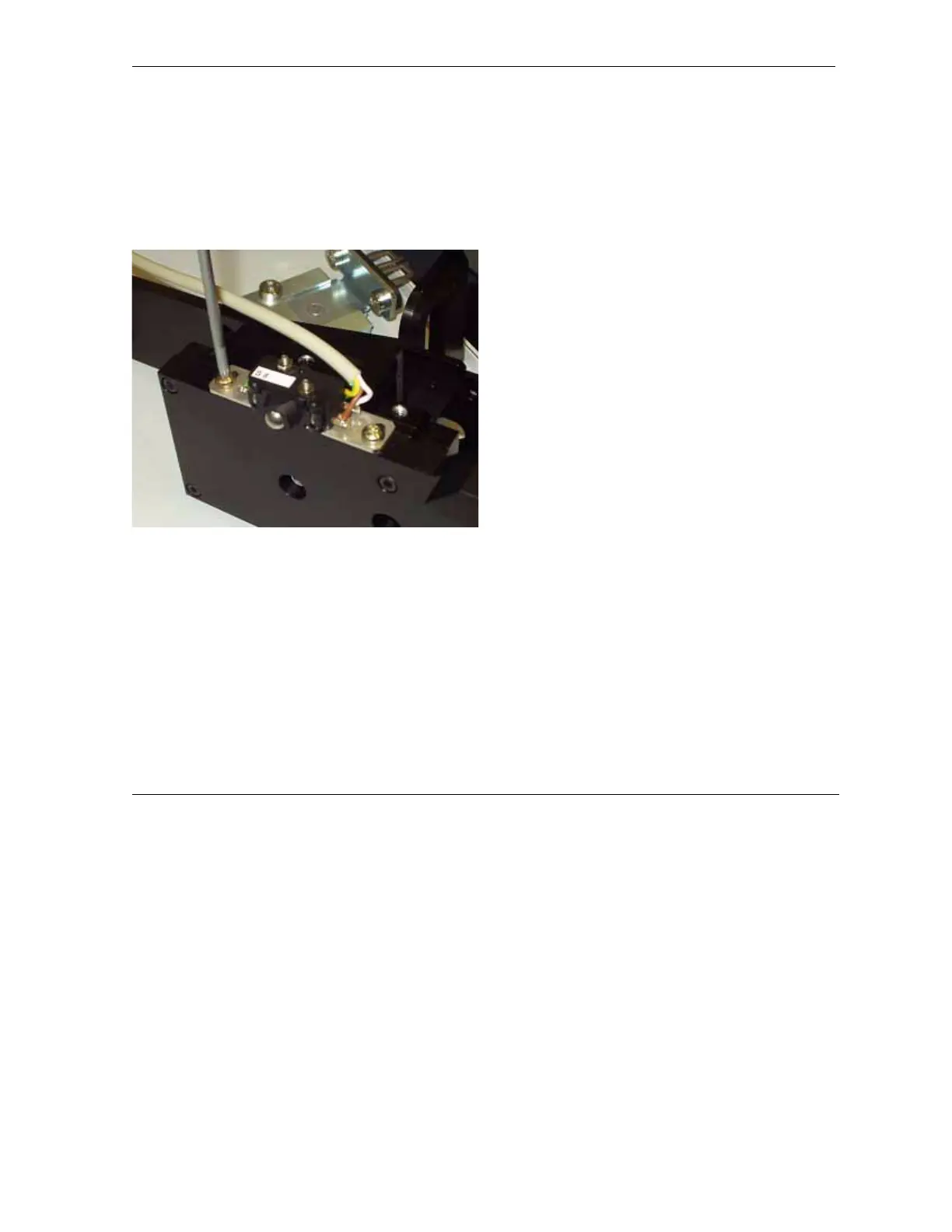
12. Mount the collision switch to the detector
mount (see Figure 5.12). Use the top posi-
tion for mounting. Align the final position
after attaching the detector to the goniome-
ter to make the switch contacts.
Figure 5.12 - Mount the collision switch to the detector
mount
13. Test the collision switch by holding up the
beam stop while moving down the detector
(2-theta). The instrument must stop moving
and display the error “theta and 2-theta in
collision” after the collision switch hits the
actuator bracket.
14. Connect the cable wiring as described in
Section 4.4.3.
15. Follow Section 4.4.4, Section 4.8 and Sec-
tion 4.8.3 through Section 4.6.
16. Replace the left side panel on the controller
rack.
17. To complete the installation, proceed to
Section 6.