VÅNTEC-1 Detector User Manual Hardware Installation for the D8 ADVANCE
M88-E01072 4 - 25
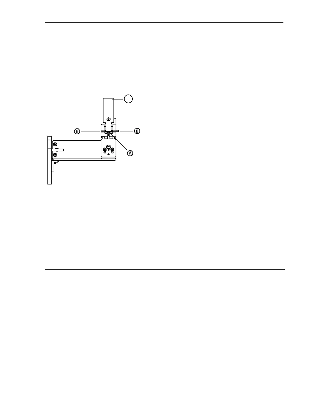
To align the beam stop:
1. Attach fluorescent paper to the upper edge
of the beam stop knife edge (item C in Fig-
ure 4.27).
2. Raise the beam stop using the thumb wheel
(item A in Figure 4.27) until the edge is
above 0° 2-theta.
Figure 4.27 - Beam stop (side view)
3. Open the shutter.
4. Observe the flux on the fluorescent paper.
4.1 Lower the room lights or cabinet lamps
to make the beam visible.
4.2 If necessary, raise the kV/mA to make
the beam clearer.
5. Lower the knife edge until the flux is clearly
distinguished on the fluorescent screen.
6. Adjust the tilt, item B in Figure 4.27, of the
knife edge until the beam appears homoge-
neous and has uniform intensity. The tilt
adjustment is comprised of opposing set-
screws. When making an adjustment, also
loosen the opposing screw.
7. Lower θ or the tube to 0°.
8. Raise the beam stop using the thumb wheel
to cut off the beam.
9. Remove the fluorescent paper from the
beam stop.
C