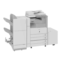
1
1
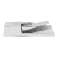
1-4
1-4
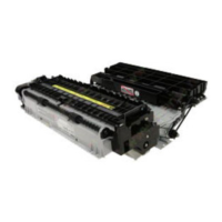
Product Outline > Names of Parts (Reader) > Cross Section > Reader Relay PCB
Product Outline > Names of Parts (Reader) > Cross Section > Reader Relay PCB
■
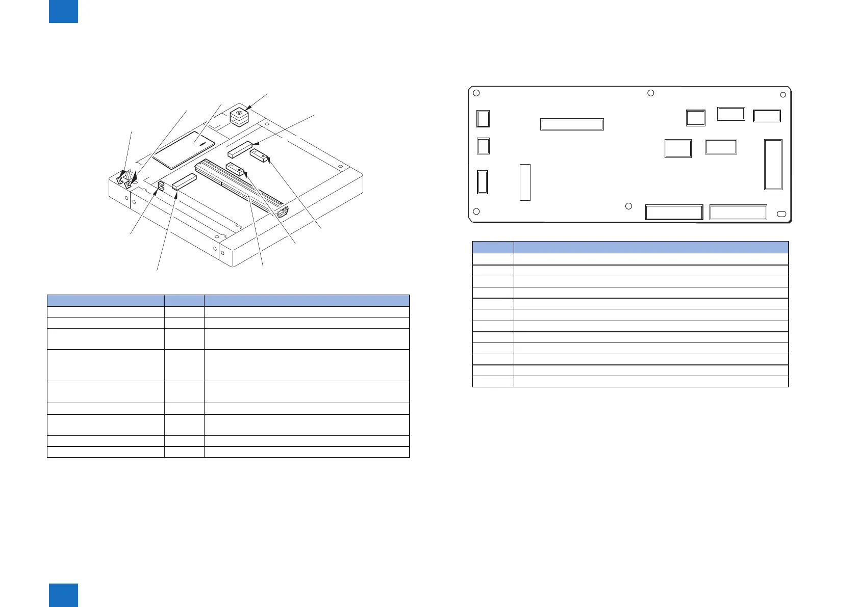
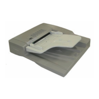
Major Components
Following shows major components of document exposure system.
[M1]Scanner Motor
[SR4]Original Size Sensor 0
[PCB1]Relay Board
[SR2]Copyboard Cover
Open/Closed Sensor(Rear)
[SR3]Copyboard Cover
Open/Closed Sensor(Front)
[SR1]CCD HP Sensor
[8]CCD Unit
[H5]Reader Heater(Option)
[H5]Reader Heater(Option)
[SR5
Item Notation Specication/function
Scanner motor M1 Pulse motor: controls the carriage drive
CCD HP sensor SR1 Detects CCD home position
Copyboard Cover Open/Closed
Sensor (front)
SR2 Ends original size identication with the copy board
cover at 15 deg
Copyboard Cover Open/Closed
Sensor (rear)
SR3 Detects the copyboard cover open/close. Starts original
size identication with the copy board cover at 5 and 25
deg.
Original Size Sensor 0 SR4 Helps identify original size(AB, INCH/AB, A)
Original Size Sensor 1 SR5 Helps identify original size(INCH/AB, INCH/A)
CCD unit - Indirect exposure by LED (LED & photoconductive
body)
Reader Heater (Option) H5 Prevents condensation on the copyboard glass
Reader relay PCB PCB1 The part of the image processing
F-1-4
T-1-2
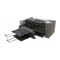
■
Reader Relay PCB
The function conguration of reader controller PCB is described below.
J504
J511
J507
J506
J509
J503
J512
J505
J502
J508
J501
J510
IC501
Jack No Description
J501 Connection to original size sensor
J502 Connection to original size sensor
J503 Power supply to DADF
J504 Communication with DADF
J505 Connection to Scanner motor
J506 Connection to original size sensor
J507 Communication with main controller PCB 2
J508 Communication with CCD
J509 Communication with DADF
J510 Connection to copyboard cover open/close sensor and CCD HP sensor
J511 Receives power from the host machine (printer unit)
J512 Communication with main controller PCB 2
F-1-5
T-1-3