6
6
6-2
6-2
Installation > How to Utilize This Installation Procedure > Symbols in the Illustration
Installation > How to Utilize This Installation Procedure > Symbols in the Illustration
How to Utilize This Installation Procedure
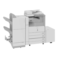
Illustrations Used in This Procedure
Illustrations used in this procedure are those of Color Image Reader Unit-D1 unless otherwise
specied.
Descriptions Used in This Procedure
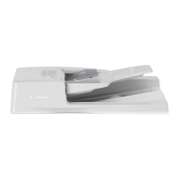
• In this procedure, Color Image Reader Unit-D1 and Color Image Reader Unit-D2 are
inclusively called the reader unit.
• For the procedure required only for the Color Image Reader Unit-D1, the relevant section
caption is followed by “[D1 only]”.
When Using the Contained Parts (Bundled Components
in the Shipping Carton)
After unpacking, conrm the parts contained in the package by referring to the illustration
of “Bundled Components” described in this procedure. The below symbol appears on the
illustration of some steps when the parts contained in the shipping carton are to be used.
Mind this symbol to be aware the parts contained in the shipping carton are to be used.
F-6-1
Symbols in the Illustration
The frequently-performed operations/works are described with symbols in this procedure.
Check the description below.
Tighten Connect
Connector Harness
Good
Connect to
the outlet
Remove the
projection
Release/
remove
the claw
Fit in/attach
the claw
Turn ON
the switch
Push Copy
Bad Check Visual
check
Disconnect Connect/
Secure
Disconnect/
Free
Remove
Sound
check
Ins t ruction on direction
(front/rear, top/bottom)
Prohibition
(Good/Bad)
Screw
Checking
instruction
F i t in the
projection
F-6-2