55
ENG
UltraCella +0300083EN - rel. 1.5 - 07.02.2015
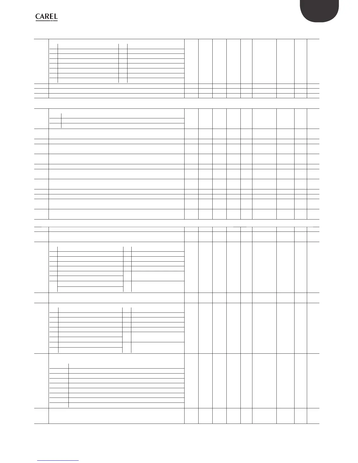
Par. Description Def Min Max UOM Type CAREL SVP Modbus
SVP
R/W page
A9 Digital input 3 (DI3) confi guration
0 Not active 8 Low pressure switch
1 Immediate external alarm 9 Do not select
2 Do not select 10 Do not select
3 Enable defrost 11 Do not select
4 Start defrost 12 Aux2 activation
5 Do not select 13 Do not select
6 Remote ON/OFF 14 Continuous cycle activation
7 Do not select
0 0 14 - I 52 91 R/W 45
Ac High temperature condenser alarm threshold 70.0 0.0 200.0 °C/°F A 22 15 R/W 62
Acd High temperature condenser alarm delay 0 0 250 min I 56 95 R/W 62
A10 Low pressure alarm delay, compressor running 3 0 60 min I 55 94 R/W
Fan
F0 Evaporator fan management
0 always on with compressor on
1 activation depends on Sd, Sv
2 variable speed fans
0 0 2 - D 20 9 R/W 47
48
F1 Fan activation temperature 5.0 -50.0 200.0 °C/°F A 23 16 R/W 36
47
Frd Fan activation diff erential 2.0 0.1 20.0 °C/°F A 24 17 R/W 47
F2 Fan activation time with compressor off 30 0 60 min I 57 96 R/W 36
47
F3 Evaporator fan during defrost
0/1=on/off
1 0 1 - D 17 6 R/W 36
Fd Post dripping time (fans off ) 1 0 30 min I 60 99 R/W 36
F4 Humidity output during defrost
0/1 = ON/OFF
1 0 1 - D 71 28 R/W 52
F5 Evaporator fans cut-off temperature
(hysteresis 1°C)
15 -50 50 °C/°F A 25 18 R/W 48
F6 Maximum fan speed 100 F7 100 % I 58 97 R/W 48
F7 Minimum fan speed 0 0 F6 % I 59 98 R/W 48
F8 Fans peak time
0 = disabled function
0 0 240 s I 176 175 R/W 48
F10 Evaporator fans forcing time at maximum speed
0 = disabled function
0 0 240 min I 177 176 R/W 48
CnF
H0 Serial address 193 0 207 - I 69 108 R/W 37
In Type of unit
0 = Normal
000-- - - R
H1 AUX1 output confi guration
0 Normally energized alarm 9 Do not select
1 Normally deenergized alarm 10 Do not select
2 Activation by AUX1 key or DI2 11 Do not select
3 Bowl resistance activation 12 Do not select
4 Auxiliary evaporator defrost 13 Second compressor step
5 Pump down valve 14 Second compressor step
with rotation
6 Condenser fan
7 Delayed compressor 15 Humidity output
8 Do not select
1 0 15 - I 61 100 R/W 42
49
52
H4 Buzzer
0/1 = enabled/ disabled
0 0 1 - D 21 10 R/W 38
H5 AUX2 output confi guration
0 Normally energized alarm 9 Do not select
1 Normally deenergized alarm 10 Do not select
2 Activation by AUX2 key or DI3 11 Do not select
3 Bowl resistance activation 12 Do not select
4 Auxiliary evaporator defrost 13 Second compressor step
5 Pump down valve 14 Second compressor step
with rotation
6 Condenser fan
7 Delayed compressor 15 Humidity output
8 Do not select
1 0 15 - I 62 101 R/W 42
49
52
H6 Terminal keys block confi guration
0 = all keys enabled
par. H6 FUNCTION
1 Set point modifi cation
2 Defrost
4-
8 AUX1 output
16 Multifunction menu (HACCP)
32 AUX2 output
64 On/Off management
128 Light management
0 0 255 - I 70 109 R/W 38
H7 BMS protocol selection
0= Carel
1= Modbus
0 0 1 - I 188 180 R/W 19
38
 Loading...


