SERViCE MANUAL
Paragraph 29 (Cont.)
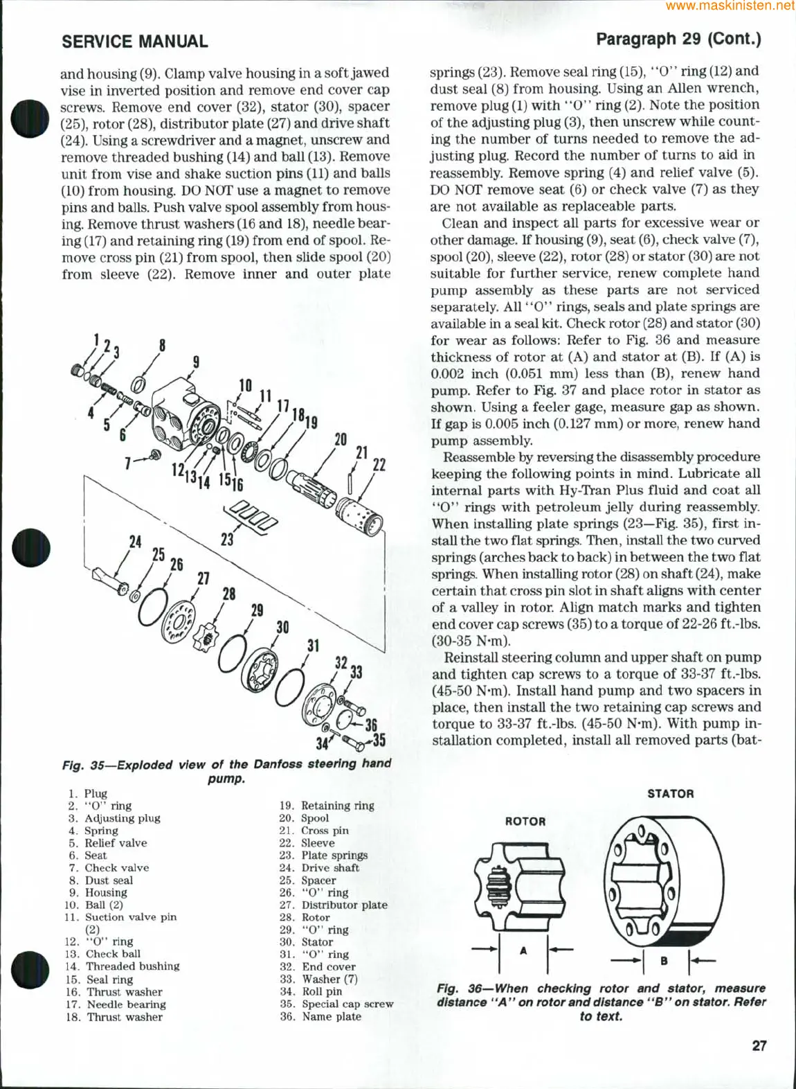
and housing
(9).
Clamp valve housing in a soft jawed
vise in inverted position and remove end cover cap
screws. Remove end cover (32), stator (30), spacer
(25),
rotor
(28),
distributor plate (27) and drive shaft
(24).
Using a screwdriver and a magnet, unscrew and
remove threaded bushing (14) and ball
(13).
Remove
unit from vise and shake suction pins (11) and balls
(10) from housing. DO NOT use a magnet to remove
pins and balls. Push valve spool assembly from hous-
ing. Remove thrust washers (16 and 18), needle bear-
ing (17) and retaining ring (19) from end of
spool.
Re-
move cross pin (21) from spool, then slide spool (20)
from sleeve (22). Remove inner and outer plate
22
r/g, 35—Exploded view of the Danfoss steering hand
1.
Plug
2.
*'O" ring
3.
AcUusting plug
4.
Spring
5.
Relief valve
6. Seat
7.
Check valve
8. Dust seal
9. Housing
10.
Ball (2)
11.
Suction valve pin
(2)
12.
*'O'* ring
13.
Check ball
14.
Threaded bushing
15.
Seal ring
16.
Thrust washer
17.
Needle bearing
18.
Thrust washer
pump.
19.
Retaining ring
20.
Spool
21.
Cross pin
22.
Sleeve
23.
Plate springs
24.
Drive shaft
25.
Spacer
26.
"0" ring
27.
Distributor plate
28.
Rotor
29. **0*'
ring
30.
Stator
31.
**0" ring
32.
End cover
33.
Washer (7)
34.
Roll pin
35.
Special cap screw
36.
Name plate
springs (23). Remove seal ring
(15),
"0" ring
(12)
and
dust seal (8) from housing. Using an Allen wrench,
remove plug
(1)
with *'O" ring
(2).
Note the position
of the adjusting plug
(3),
then unscrew while count-
ing the number of turns needed to remove the ad-
justing plug. Record the number of turns to aid in
reassembly. Remove spring (4) and relief valve (5).
DO NOT remove seat (6) or check valve (7) as they
are not available as replaceable parts.
Clean and inspect all parts for excessive wear or
other damage. If housing
(9),
seat
(6),
check valve (7),
spool
(20),
sleeve (22), rotor (28) or stator (30) are not
suitable for further service, renew complete hand
pump assembly as these parts are not serviced
separately. All '*0" rings, seals and plate springs are
available in a seal kit. Check rotor (28) and stator (30)
for wear as follows: Refer to Fig. 36 and measure
thickness of rotor at (A) and stator at (B). If (A) is
0.002 inch (0.051 mm) less than (B), renew hand
pump. Refer to Fig. 37 and place rotor in stator as
shown. Using a feeler gage, measure gap as shown.
If gap is 0.005 inch (0.127 mm) or more, renew hand
pump assembly.
Reassemble by reversing the disassembly procedure
keeping the following points in mind. Lubricate all
internal parts with Hy-Tran Plus fluid and coat all
**0'*
rings with petroleum jelly during reassembly.
When installing plate springs (23—Fig. 35), first in-
stall the two flat springs. Then, install the two curved
springs (arches back to back) in between the two flat
springs. When installing rotor (28) on shaft
(24),
make
certain that cross pin slot in shaft aligns with center
of a valley in rotor. Align match marks and tighten
end cover cap screws (35) to a torque of 22-26 ft.-lbs.
(30-35 N-m).
Reinstall steering column and upper shaft on pump
and tighten cap screws to a torque of 33-37 ft.-lbs.
(45-50 N-m). Install hand pump and two spacers in
place, then install the two retaining cap screws and
torque to 33-37 ft.-lbs. (45-50 N-m). With pump in-
stallation completed, install all removed parts (bat-
STATOR
ROTOR
Fig. 36—When checking rotor and
stator,
measure
distance "A" on rotor and distance "B*'on
stator.
Refer
to
text.
27



 To Next Page