SERViCE MANUAL
Paragraph 104 (Cont.)
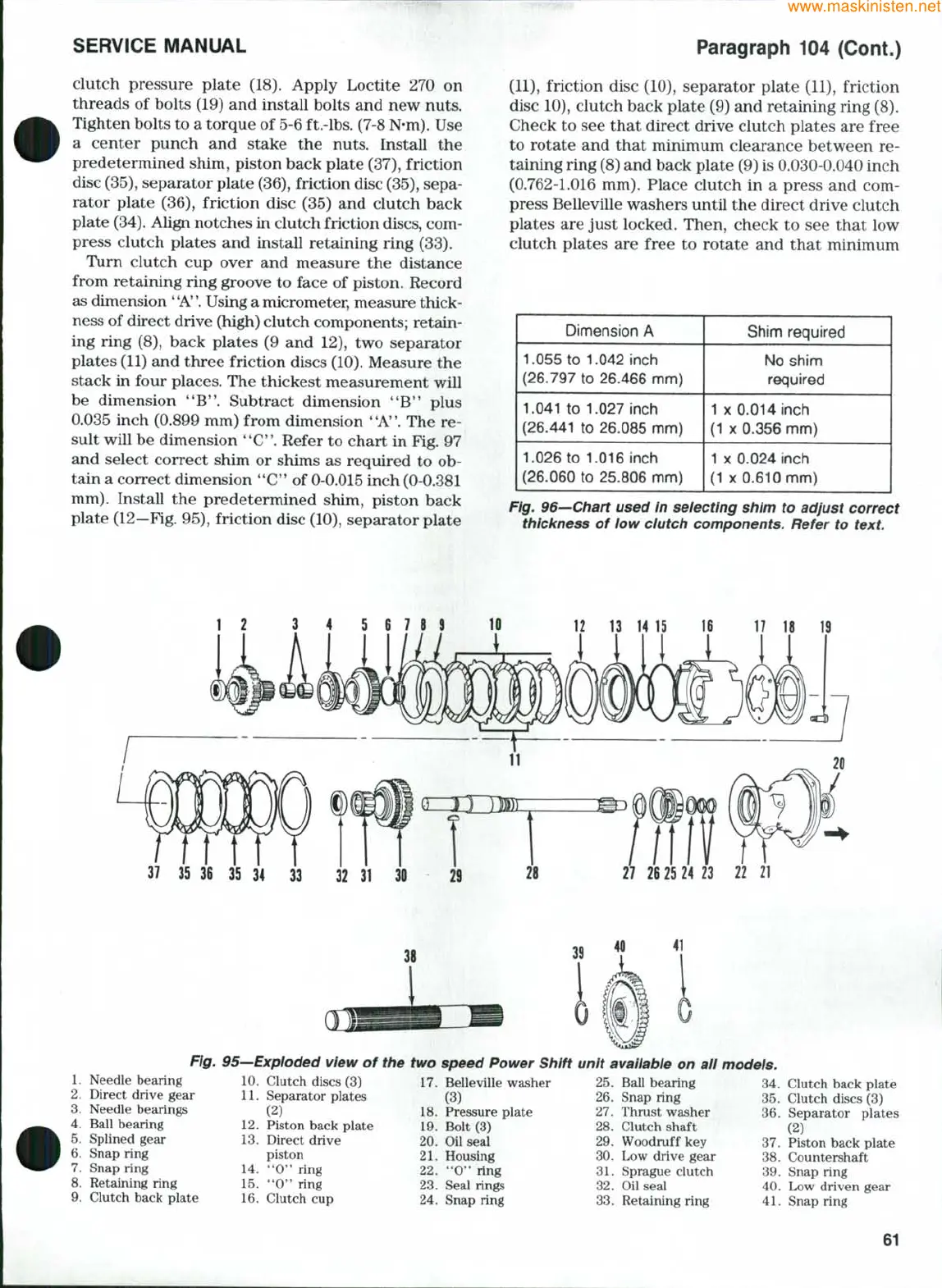
clutch pressure plate (18). Apply Loctite 270 on
threads of bolts (19) and install bolts and new nuts.
Tighten bolts to a torque of 5-6 ft.-lbs. (7-8
N-m).
Use
a center punch and stake the nuts. Install the
predetermined shim, piston back plate (37), friction
disc
(35),
separator plate
(36),
friction disc
(35),
sepa-
rator plate (36), friction disc (35) and clutch back
plate
(34).
Align notches in clutch friction discs, com-
press clutch plates and install retaining ring (33).
Turn clutch cup over and measure the distance
from retaining ring groove to face of piston. Record
as dimension
*
'A''.
Using a micrometer, measure thick-
ness of direct drive (high) clutch components; retain-
ing ring (8), back plates (9 and 12), two separator
plates (11) and three friction discs
(10).
Measure the
stack in four places. The thickest measurement will
be dimension
**B*'.
Subtract dimension **B'' plus
0.035 inch (0.899 mm) from dimension "A". The re-
sult will be dimension **C. Refer to chart in Fig. 97
and select correct shim or shims as required to ob-
tain a correct dimension ''C" of 0-0.015 inch (0-0.381
mm).
Install the predetermined shim, piston back
plate (12—Fig. 95), friction disc (10), separator plate
(11),
friction disc (10), separator plate (11), friction
disc 10), clutch back plate (9) and retaining ring (8).
Check to see that direct drive clutch plates are free
to rotate and that minimum clearance between re-
taining ring (8) and back plate (9) is 0.030-0.040 inch
(0.762-1.016 mm). Place clutch in a press and com-
press Belleville washers until the direct drive clutch
plates are just locked. Then, check to see that low
clutch plates are free to rotate and that minimum
Dimension A
1.055 to 1.042 inch
(26.797 to 26.466 mm)
1.041 to 1.027 inch
(26.441 to 26.085 mm)
1.026 to 1.016 inch
(26.060 to 25.806 mm)
Shim required
No shim
required
1
X
0.014 Inch
(1
X
0.356 mm)
1
X
0.024 inch
(1
X
0.610 mm)
Fig. 96—Chart used in selecting shim to adjust correct
thickness of low clutch components. Refer to
text.
12
13
14 15
16 17 18 19
12
3 4 5 6 7 8 9 10
37
35 36 35 34 33 32 31 30 29
27 26 25 24 23
22 21
Fig-
1.
Needle bearing
2.
Direct drive gear
3.
Needle bearings
4.
Ball bearing
5.
Splined gear
6. Snap ring
7.
Snap ring
8. Retaining ring
9. Clutch back plate
95—Exploded view of the
10.
Clutch discs (3)
11.
Separator plates
(2)
12.
Piston back plate
13.
Direct drive
piston
14.
"0" ring
15.
"0" ring
16.
Clutch cup
two speed Power Shift
17.
Belleville washer
(3)
18.
Pressure plate
19.
Bolt (3)
20.
Oil seal
21.
Housing
22.
"0" ring
23.
Seal rings
24.
Snap ring
unit avaiiabie on all
25.
Ball bearing
26.
Snap ring
27.
Thrust washer
28.
Clutch shaft
29.
Woodruff key
30.
Low drive gear
31.
Sprague clutch
32.
Oil seal
33.
Retaining ring
models.
34.
Clutch back plate
35.
Clutch discs (3)
36.
Separator plates
(2)
37.
Piston back plate
38.
Countershaft
39.
Snap ring
40.
Low driven gear
41.
Snap ring
61



 To Next Page