Paragraph 127 (Cont.)
CASE/INTERNATIONAL
Inspect sleeve
(28),
roller bearing
(29)
and idler gear
(17),
if so equipped, and renew as necessary. Sleeve
has a slot which must be aligned with pin in shaft
(22) or (52) during assembly.
Reassemble and reinstall pto by reversing disassem-
bly and removal procedures.
Tb remove the 540 rpm output shaft (8), gear (9),
idler shaft (15) and idler gear (17), first remove hy-
draulic lift assembly as outlined in paragraph 137 or
138.
Remove snap ring (10) and unbolt bearing and
seal retainer (2). Withdraw output shaft assembly
and remove gear (9) through top opening. Install a
cap screw in rear of idler shaft (15), pull idler shaft
from rear of frame and remove idler gear (17) from
above. Use new
**0*'
ring
(14),
oil seal and gasket and
reinstall by reversing the removal procedure.
1.
2.
3.
4.
5.
6.
7.
8.
9.
10.
11.
12.
13.
14.
15.
16.
17.
18.
19.
20.
21.
22.
23.
24.
25.
26.
27.
28.
29.
30.
31.
32.
33.
34.
35.
36.
37.
38.
39.
40.
41.
42.
43.
44.
45.
46.
47.
48.
49.
50.
51.
52.
Shaft cover
Bearing
&
seal
retainer
Gasket
Oil seal
Snap ring
Washer
Ball bearing
540 rpm shaft
Gear
Snap ring
Snap ring
Needle bearing
Snap ring
"0"
ring
Idler shaft
Needle bearing
Idler gear
Cover
Gasket
Snap ring
Bali bearing
Lower drive
shaft (540 rpm)
Gear
Snap ring
Seal rings
Bushing
Needle bearing
Sleeve
Roller bearing
Idler gear
Clutch cup
Piston
*'O*'
ring (inner)
**0"
ring (outer)
Brake ring
Piston back plate
Friction disc
Drive plates
Return springs
Clutch back plate
Snap ring
Thrust washer
Clutch hub
Snap ring
Needle bearing
Shaft safety cover
Bearing
&
seal
retainer
Gasket
Oil seal
Snap ring
Ball bearing
1000 rpm shaft
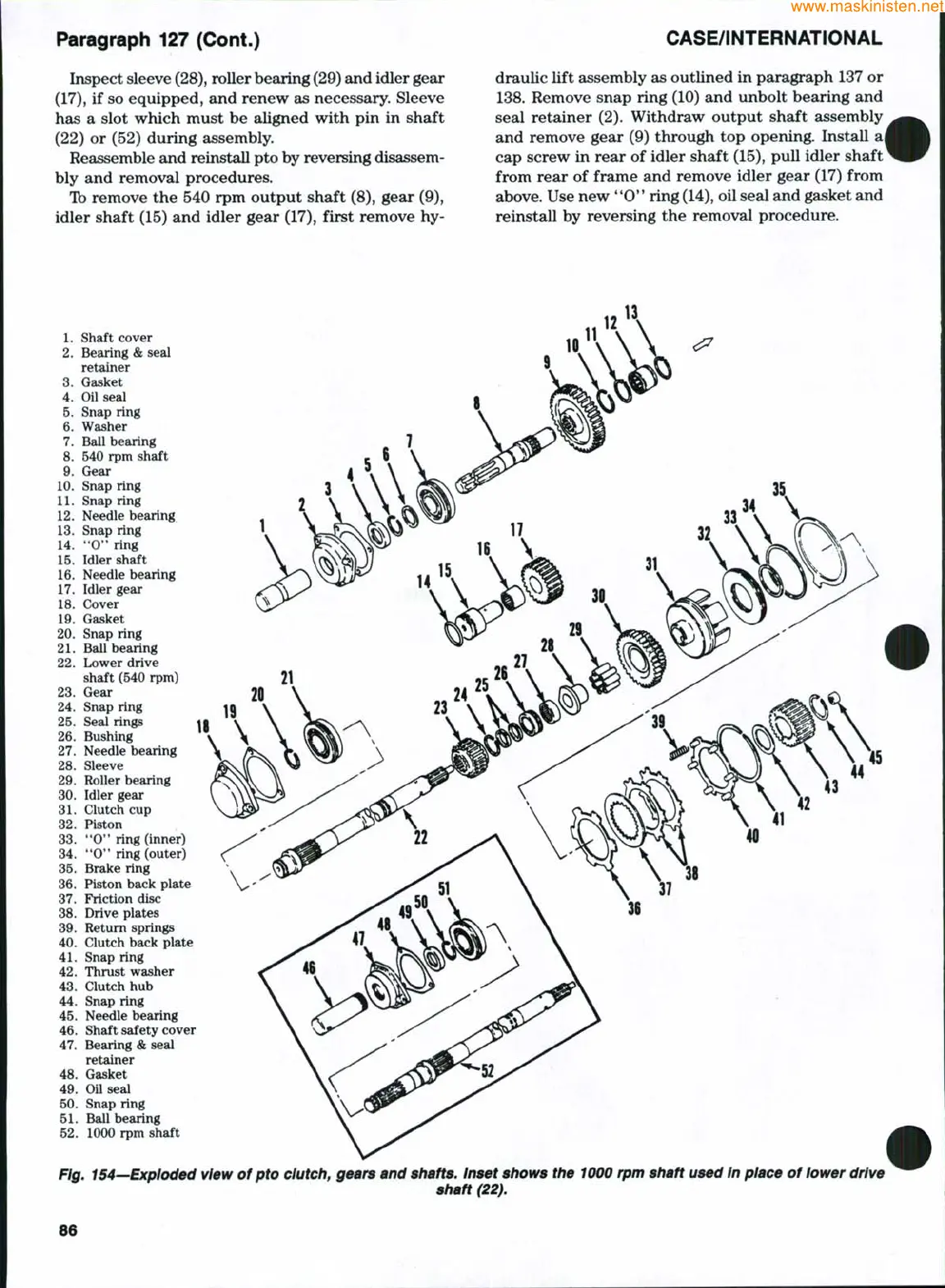
Fig. 154—Exploded view of pto clutch, gears and shafts. Inset shows the 1000 rpm shaft used In place of lower drive
shaft (22).
86
 Loading...


