SECTION 21 - TRANSMISSION 267
2.15 FAULT FINDING
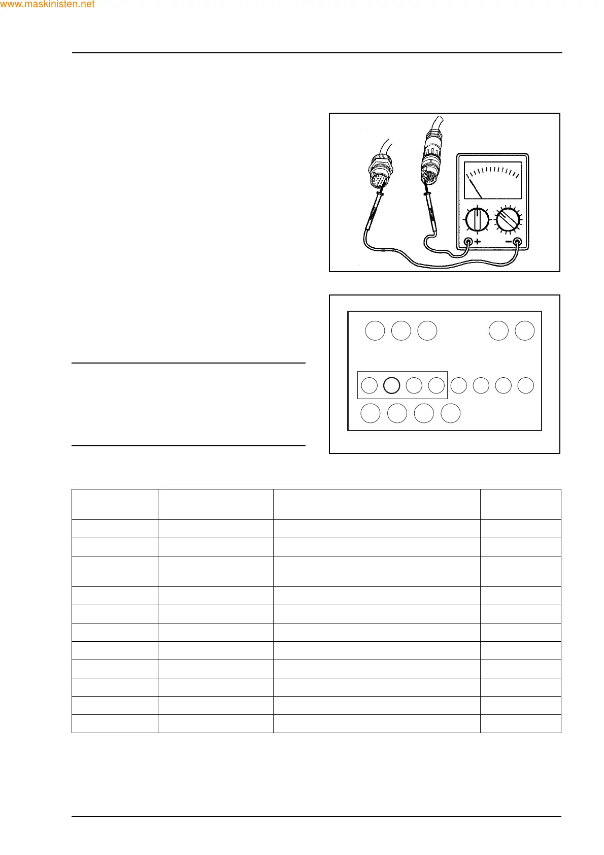
Before attempting any fault finding ensure you have
a suitable multimeter for checking component conti-
nuity. When fault finding remember that with an elec-
trical concern it is often a minor fault that may have
occurred and could be as simple as:
Z Poor continuity between connector pins.
Z Condensation in the connectors.
Z Disconnected cables.
Z Damaged or broken wires all of which could result
in a no drive situation but easily remedied when
found and corrected.
It should also be remembered that mechanical prob-
lems could result in fault codes appearing on the
LED display.
INDICATION OF FAULTS
In case a fault is present during normal operation
and is detected by the microprocessor, both the T-
LED and N-LED may be blinking in some way as
shown in the table below.
NOTE: on an open circuit or on a battery connection
(+), at the ON/OFF outputs, a detection is made only
when the corresponding output is in the OFF posi-
tion.
Also a short to ground is only detected while the out-
put is on.
LED - T
(Orange)
LED - N
(Red)
CONDITION SITUATION
Off Off Normal operation -
Off On Normal operation - N selected -
Off Blinks Blinks Normal operation - N selected/speed
too high
-
On Off Diagnostic mode was activated at power up -
On On Controller in RESET - malfunction Fault
On Blinks Self calibration in progress -
Blinks On Last fault currently shown on display Fault
Blinks Blinks slower Input fault detected Fault
Blinks Blinks in phase Non critical output fault detected Fault
Blinks Blinks faster Safety critical output fault detected Fault
Blinks fast Blinks out of phase System shutdown - Neutral till power down Fault
F28292
F28358
F
1234
12345678
NR T N
 Loading...


