SECTION 50 - CAB HEATING AND AIR CONDITIONING 5
2. CAB HEATING
2.1 DESCRIPTION AND OPERATION
Cab heating
The cab is heated by a radiator mounted below the
cab seat, which is supplied hot water from the engine
coolant system. A blower motor mounted behind the
cab radiator is used to transfer the heat into the cab.
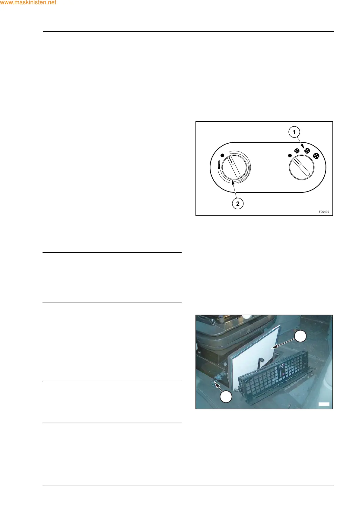
Heater blower control
The three speed blower is controlled by switch (1)
mounted in the instrument console to the right of the
cab seat. Turn the switch clockwise to the first posi-
tion for slow speed. Further rotation of the switch in
a clockwise direction selects medium and fast
speeds. The blower draws outside air from beneath
the cab floor and through a filter medium into the
cab.
Temperature control
The temperature of the air from the radiator is adjust-
ed by rotation of the control knob (2) which opens or
closes the radiator valve increasing or decreasing
the water flow as required. Turn the control clock-
wise to increase the temperature of air from the
heater and counter clockwise to reduce the temper-
ature.
SWARNING
The cab air filters are designed to remove dust from
the air but may not exclude chemical vapour. When
working in an enclosed area ensure there is ade-
quate ventilation as exhaust fumes can suffocate
you.
Cab air filter
Before servicing the air filter situated under the driv-
ers seat, switch off the blower and close all windows
and one door. Forcibly close the other door. The re-
sulting back pressure will dislodge loose dirt from
the underside of the filters. To remove the filter (3)
release the retaining straps (4) and remove the filter
element. Ensure the element, and sealing faces are
not damaged on removal.
IMPORTANT: in humid conditions, such as occur on
most early mornings, do not switch on the blower pri-
or to servicing the filters. Damp particles drawn into
the filter may solidify and prove difficult to remove
without washing.
The filter element is made of specially treated paper
with a sealing strip bonded to the outer face.
Clean this element by blowing with compressed air
from the clean side through to the dirty side. The
compressed air should not exceed 2 bar and the air
line nozzle should be at least 300 mm from the ele-
ment.
F29325
3
4