SECTION 27 - REAR AXLE 3
1. REAR AXLE 2WS
1.1 DESCRIPTION AND OPERATION
The rear axle is a rigid axle and is fixed by 4 screws
to the chassis with a torque value of 800 Nm.
It incorporates the following features:
Z mechanically operated differential unit;
Z hydraulically operated oil immersed foot brakes fit-
ted with four disc brakes;
Z planetary gear carrier with 3 gears.
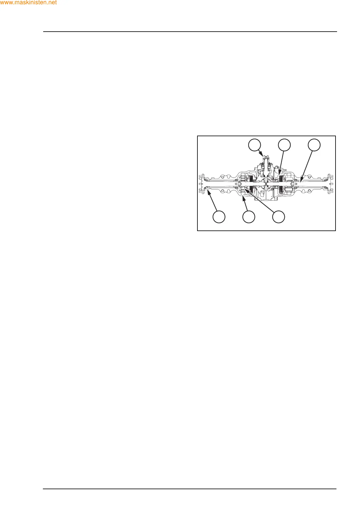
Power from the transmission output shaft is trans-
mitted to the rear axle through the flange (1), the
brake pads (2) and the half shaft (3) to the rear fire.
The pinion is located on preloaded bevel roller bear-
ings.
The differential is located on two roller bearings, the
right hand bearing supported by an internal web of
the axle centre housing.
The crown is fixed to the differential housing. Drive
from the housing is transmitted through a four pinion
differential to sun gear shafts which are splined into
the differential side gears.
The differential lock sliding coupling is located on the
splines of the right hand differential side gear. The
coupling has dog teeth which engage with the dog
teeth on the differential housing lock adaptor.
If the dog teeth are not aligned, the spring engage-
ment link will be preloaded, ensuring rapid and full
tooth engagement when the dog teeth align.
The differential lock will remain engaged due to dog
tooth side loading as long as the rear wheels have
unequal traction.
The return spring disengages the lock when both
wheels have equal traction or drive is disengaged.
The brakes are mounted on the final reduction sun
gears. These brakes are wet disc type with hydraulic
piston actuator operated by foot pedals, independ-
ently for turning assistance, or together for transport.
The gears (4) are mounted in a carrier and are posi-
tioned around the sun gear and within the ring gear
(5). The rear axle shafts (3) are located into the inter-
nal splines in the carriers.
As the sun gear is driven by the differential, the gears
revolve inside the stationary planetary ring gear and
drive the carrier and axle shaft at reduced speed.
The rear axle shaft is supported on taper roller bear-
ings (6). Preload is adjusted by means of selective
shims held under the retaining plate and screws.
1 2 3
6 5 4
F29546