46 SECTION 50 - CAB HEATING AND AIR CONDITIONING
3.6 EVACUATING THE SYSTEM
IMPORTANT: a system in which the refrigerant has
been recovered to facilitate repairs, must be evacu-
ated before new refrigerant is installed.
Air and moisture are removed by evacuating the
system using a vacuum pump.
The automatic recycling, recharge and evacuation
stations or evacuating and charging stations availa-
ble throughout the air conditioning industry incorpo-
rate a vacuum pump within the assembly. If this type
of equipment is not available a separate vacuum
pump and manifold gauge set must be used.
As the system is evacuated the boiling point of any
moisture within the system is similarly lowered. As
the vacuum increases, the boiling point decreases
to below that of the ambient temperature and, con-
sequently, the moisture is boiled away.
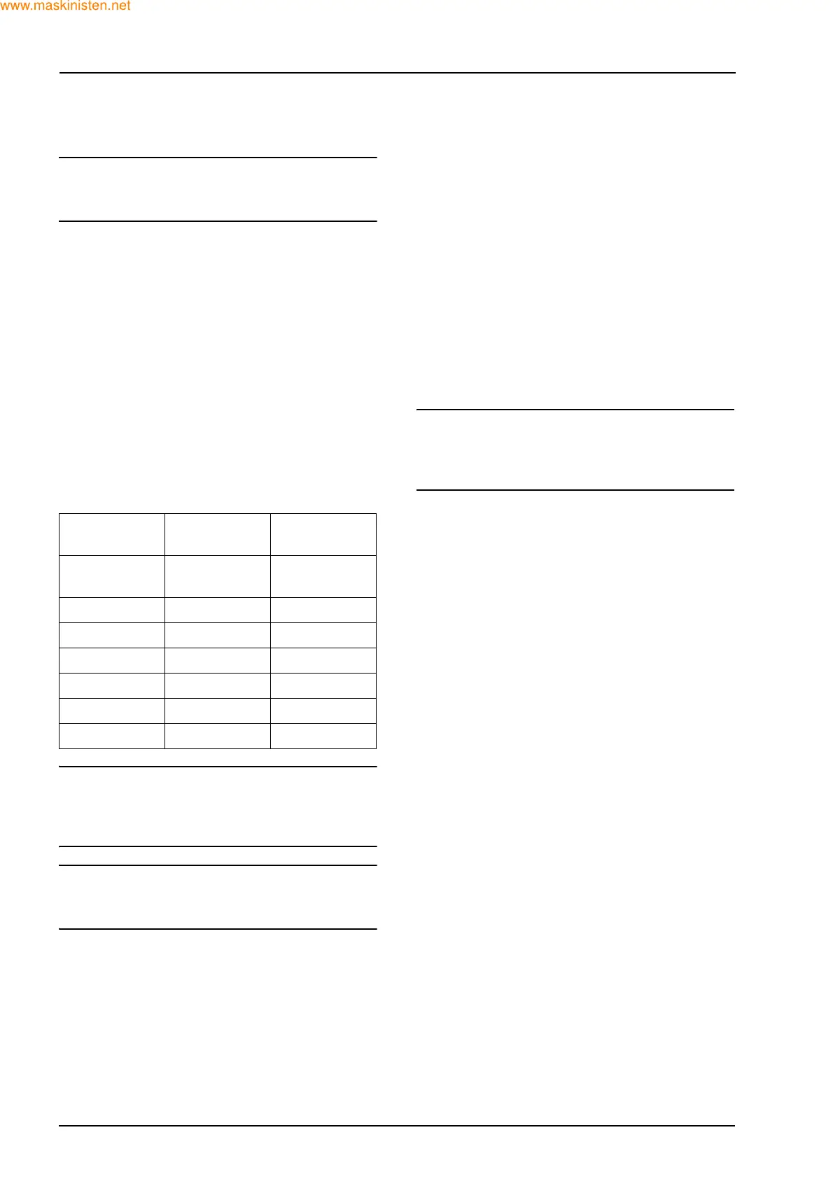
The relationship of system vacuum to the boiling
temperature at which the water vapour is removed
from the system is as follows:
NOTE: for every 305 m above sea level, the vacuum
gauge reading must be corrected by adding 2.54 cm
of mercury to compensate for the change in atmos-
pheric pressure.
IMPORTANT: be sure the system is completely dis-
charged as refrigerant will damage the vacuum
pump.
1. If the manifold gauge set is being used connect
the low and high sides of the manifold to the low
and high sides of the vehicle air conditioning
system as described for discharging the system.
Connect the manifold centre hose to the vacu-
um pump suction port as per the manufacturers
instructions.
Fully open both the low and high side gauge
shut off valves.
2. If a combined recovery/evacuation unit is to be
used attach the unit to the air conditioning sys-
tem in accordance with the manufacturers in-
structions. Be sure to read all installation and
operating instructions carefully before starting
the unit.
3. After starting the evacuation cycle, note the low
side gauge to be sure the system pulls down
into a vacuum.
4. Time the evacuation for a minimum of 30 min-
utes from the point when lowest vacuum is at-
tained.
5. Thirty minutes later when the low side gauge at-
tains the lowest steady vacuum, stop the evac-
uation process.
NOTE: the vacuum pump achieves ultimate vacu-
um with the vented exhaust valve closed. Do not
evacuate too quickly as oil may be drawn from the
system.
6. Check the system by closing the gauge shut-off
valves, turning the vacuum pump off and noting
the low side gauge reading. A loss of more than
5 cm of vacuum in 5 minutes indicates either a
leak or moisture in the system.
7. If the gauge needle remains stationary and the
vacuum is maintained for 3-5 minutes, close
both the high and low side manifold hand
valves, turn off and disconnect the centre hose
from the pump. The system is now ready for
charging.
8. If a leak is detected, charge the system with ap-
proximately 400 g of refrigerant, see charging
the system and locate the leak using a leak de-
tector.
9. Once the leak is located discharge and recover
the refrigerant in the system, repair the leak,
then repeat the evacuation procedure.
System
Vacuum
System
Vacuum
Temperature
In
Mercury
In Cm. of
Mercury
°C
28.0 71.0 38
28.9 73.4 27
29.4 74.6 16
29.7 75.4 5
29.8 75.7 -7
29.9 75.9 -18