SECTION 35 - HYDRAULIC SYSTEM 13
2. HYDRAULIC PUMP
2.1 DESCRIPTION AND OPERATION
There are two types of pumps:
Z for 97 HP engine;
Z for 110 HP engine.
The gear type hydraulic pump assembly is mounted
on the rear of the transmission and driven by a shaft
directly connected to the engine flywheel splined to
the torque converter housing.
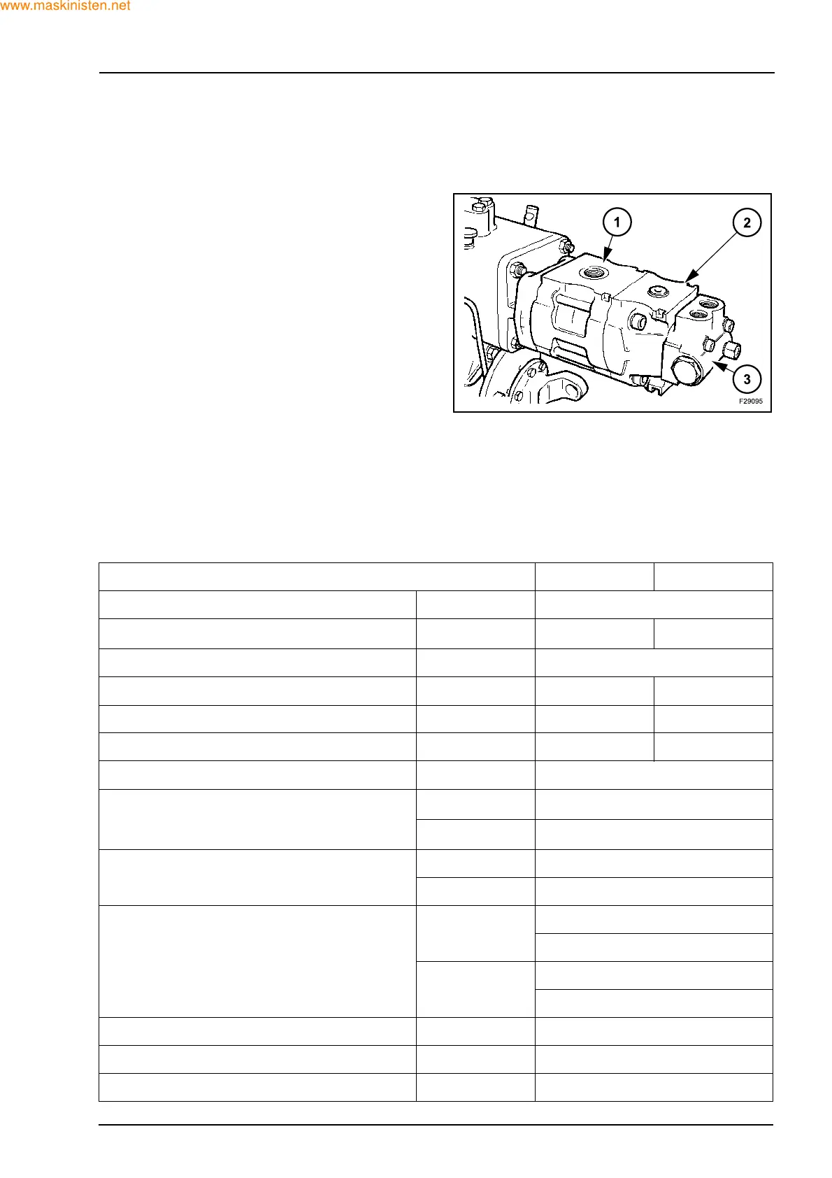
The pump comprises of two pumping elements, the
front pump (1) rear pump (2) and load sensing steer-
ing flow divider control valve (3).
Oil is drawn through the common inlet port into both
pumping elements.
Front pump flow is directed to the loader and back-
hoe attachment control valves and to the sideshift
locking cylinders.
Rear pump flow passes through the flow divider
valve which maintains priority oil flow to the steering
system with remaining flow directed for operation of
stabilizers, loader and backhoe elements.
2.2 SPECIFICATIONS
PUMP (97 HP ENGINE) 1st PUMP 2nd PUMP
Direction of rotation (looking on drive shaft) Clockwise (D)
Displacement
40.258 (cm
3
/rev) 35.427 (cm
3
/rev)
Inlet pressure range for pump 0.7 - 3 bar
Maximum continuous pressure P 1 260 bar 260 bar
Maximum intermittent pressure P 2 280 bar 280 bar
Maximum peak pressure P 3 300 bar 300 bar
Operating temperature -25 to -80 (°C)
Speed
min P1
350 (min
-1
)
max P1
3000 (min
-1
)
Viscosity range
recommended 12 to 100 mm 2/s (cSt)
permitted max 750 mm 2/s (cSt)
Contamination class
Dp > 200 bar
bx = 75 - 10 mm
8 - Nas 1638
19 / 17 /14 - ISO 4406
Dp < 200 bar
bx = 75 - 25 mm
10 - Nas 1638
21 / 19 /16 - ISO 4406
Relief valve 177 ± 3 bar
Stand by pressure load sensing valve 7 bar
Weight 30 kg