SECTION 17 - TORQUE CONVERTERS 3
1. POWERSHUTTLE TORQUE CONVERTER
1.1 DESCRIPTION AND OPERATION
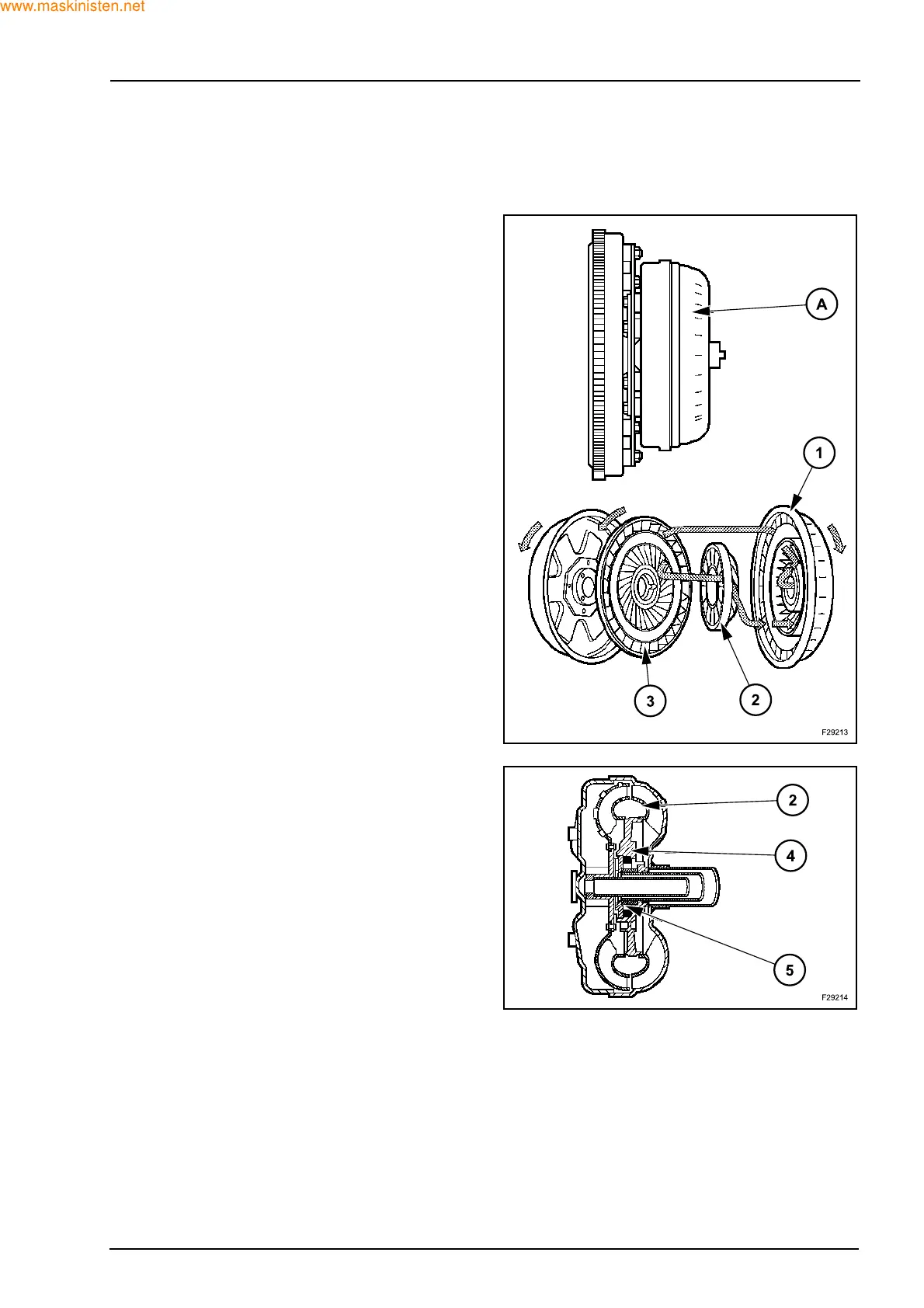
The torque converter is the connection between the
engine and the transmission and is hydraulically ac-
tuated. The main parts of the torque converter (A)
are the impeller (pump), the turbine, the stator and
the front and rear covers. The impeller is integral
with the rear cover and is driven by the engine fly-
wheel by means of a drive plate. The stator, is
splined to a stationary shaft (stator support) through
a one-way clutch that permits the stator to rotate
only in the same direction as the impeller. All of the
converter parts are enclosed in an oil-filled housing.
The front and rear cover, being welded together,
form the housing. The turbine (2), splined to the front
input shaft, is splined to a stationary shaft (stator
support) through a one-way clutch that permits the
stator (3) to rotate only in the same direction as the
impeller (1). All of the converter parts are enclosed
in an oil-filled housing. When the engine is running,
the oil in the converter flows from the impeller (1) to
the turbine (2) and back to the impeller through the
stator (3). This flow produces a maximum torque in-
crease. When enough oil flow is developed by the
impeller, the turbine begins to rotate, driving the
front input shaft. The torque multiplication gradually
decreases as turbine speed approaches impeller
speed, and becomes 1 to 1 when the turbine is being
driven at nine tenths impeller speed.
When the turbine (2) is rotating at approximately nine
tenths impeller speed, the converter stops multiplying
torque because the oil is now acting on the rear face
of the stator blades (4). The action of the oil on the
rear face of the stator unlocks the one-way clutch (5),
permitting the stator to rotate in the same direction as
the turbine (2) and impeller (1). Through this action
the converter becomes an efficient fluid coupling by
transmitting engine torque from the impeller to the tur-
bine. To achieve optimum operation the engine per-
formance, transmission ratios, hydraulic power
delivery and converter torque multiplication are all
“Matched” to provide the necessary vehicle drive
torque when required. When the turbine is rotating
less than nine tenths impeller speed (1), the converter
is multiplying torque through the action of the stator
(3). This action, produced by oil acting on the front
face of the stator blades, tends to rotate the stator in
the opposite direction of the impeller (1) and turbine
(2). However, the one-way clutch prevents this oppo-
site rotation and allows the stator to direct oil back to
the impeller, thereby producing torque multiplication.
Maximum torque multiplication is achieved when the
impeller is driven at stall speed and the turbine is sta-
tionary.