SECTION 50 - CAB HEATING AND AIR CONDITIONING 15
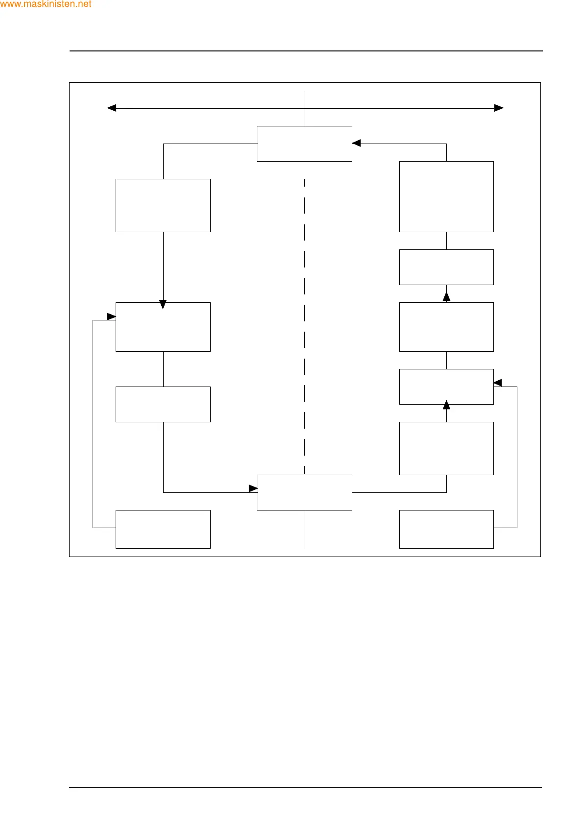
Air conditioning flow diagram
It can now be seen that the principal components of
an air conditioning system are:
Z Refrigerant
Z Compressor
Z Condenser
Z Receiver dryer
Z Expansion valve
Z Evaporator
The figure in the previous page uses the examples
above to illustrate the air conditioning cycle.
The figure in the this page shows in schematic form
the flow of refrigerant through the five major compo-
nents of an air conditioning system.
Refrigerant is drawn into the compressor as a cool,
low pressure vapour which is compressed and then
pumped out as a hot, high pressure vapour to the
condenser.
As the hot, high pressure vapour passes through the
condenser core it gives off heat to the cooler outside
air, being drawn past the fins by the engine cooling
fan.
LOW PRESSURE SIDE HIGH PRESSURE SIDE
EXPANSION
VALVE
LOW
TEMPERATURE
HIGH PRESSURE
LIQUID FILTERED
AND MOISTURE
REMOVED
LIQUID ATOMIZED
AT A LOWER
TEMPERATURE
RECEIVER
DRYER
EVAPORATOR
LOWER
TEMPERATURE
HIGH PRESSURE
LIQUID
CONDENSER
WARM LOW
PRESSURE VAPOUR
HIGH
TEMPERATURE
HIGH PRESSURE
VAPOUR
COMPRESSOR
HEAT FROM INSIDE
CAB MOVES TO
REFRIGERANT
HEAT MOVES TO
OUTSIDE AIR FROM
REFRIGERANT