102 SECTION 55 - ELECTRICAL SYSTEM
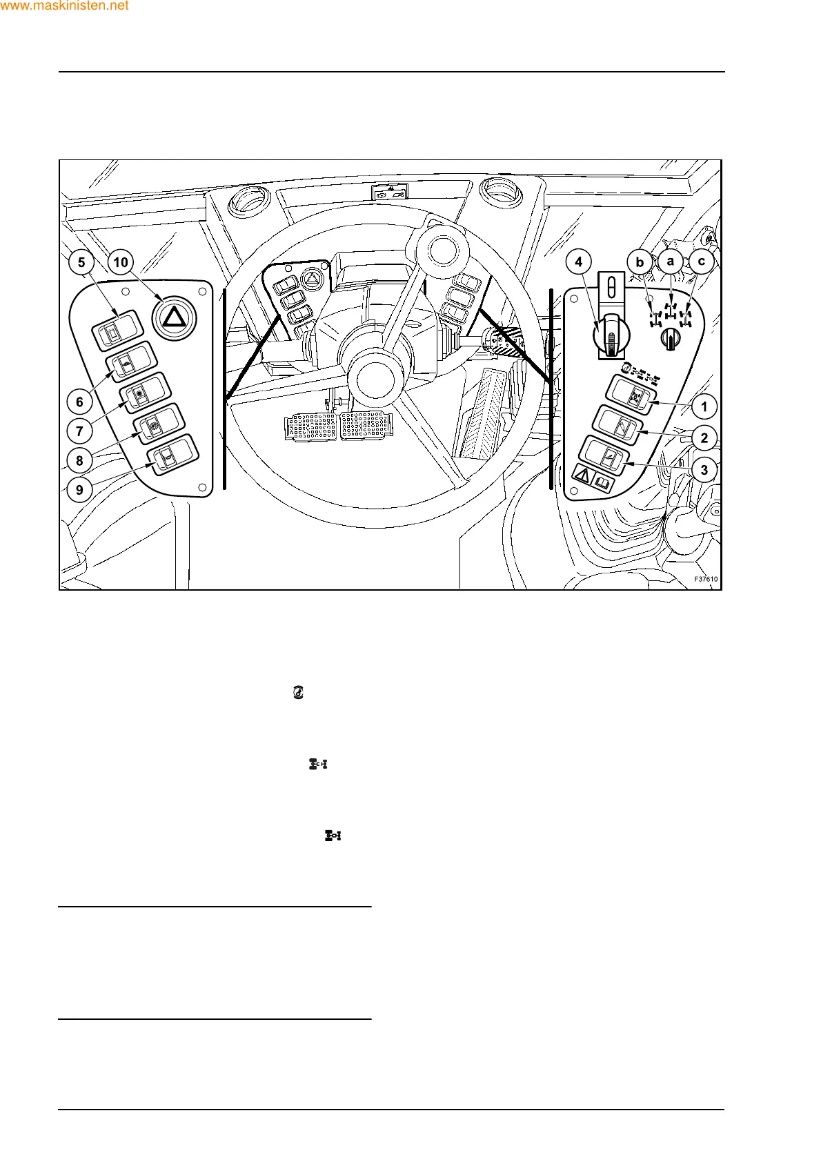
3.2 FRONT CONTROL PANELS (695SR)
1. 2WD/4WD SWITCH
This switch is used to engage or disengage the
four wheel drive.
This switch has three positions:
- First position (by pushing the button on
the left):
rear wheel drive with braking on 4 wheels
(lamp off, it turns on when braking).
- Second position (by pushing the button
on the right):
rear wheel drive with braking on rear wheels
(lamp off).
- Third position (by pushing again the but-
ton on the right):
4 wheel drive with braking on 4 wheels (lamp
on).
NOTE: when the 4WD switch is in OFF position and
the two brake pedals are pressed at the same time,
the 4 wheel drive is engaged automatically (at
speeds higher than 3 km/h) to ensure braking on the
4 wheels; it disengages when the brake pedals are
released.
2. HAND-HELD AUXILIARY HYDRAULIC AT-
TACHMENT SWITCH (Optional)
This switch has two positions:
- The first position is OFF.
- The second position is ON and enables the
auxiliary hydraulic attachments.
3. LOADER ATTACHMENT LOCKING SWITCH
(Optional)
When operated, this switch is for preventing any
movement of the loader attachment during trav-
el.
4. STEER MODE SWITCH
This switch has a locking cover and is used to
select “Road”, “4 wheel steer” or “Crab steer”.
This switch has three positions:
- Position (a) = Road
- Position (b) = 4 wheel steer
- Position (c) = Crab steer
2
 Loading...


