SECTION 55 - ELECTRICAL SYSTEM 153
CHECKING THE ALTERNATOR COMPONENTS
Checking of components must be done only if the
PRELIMINARY TESTS reveal an alternator defect
which relates to the following components:
Z Regulator
Z Continuity of the rotor field winding
Z Brushes, springs and slip rings
NOTE: these checks may be carried out without re-
moving the alternator from the vehicle.
The alternator must be removed to check the other
components of the alternator.
Refer to the “Removal” section in this chapter.
IMPORTANT: before disconnecting the cables from
the alternator, make sure that the ignition is turned
off (key on “off”) and the negative cable of the battery
is disconnected.
Required devices:
Z 12 V battery
Z Multimeter
Z 2.2 W test lamp
CHECKING THE REGULATOR AND THE FIELD
CIRCUIT OF THE REGULATOR
Z Disconnect all cables from the alternator.
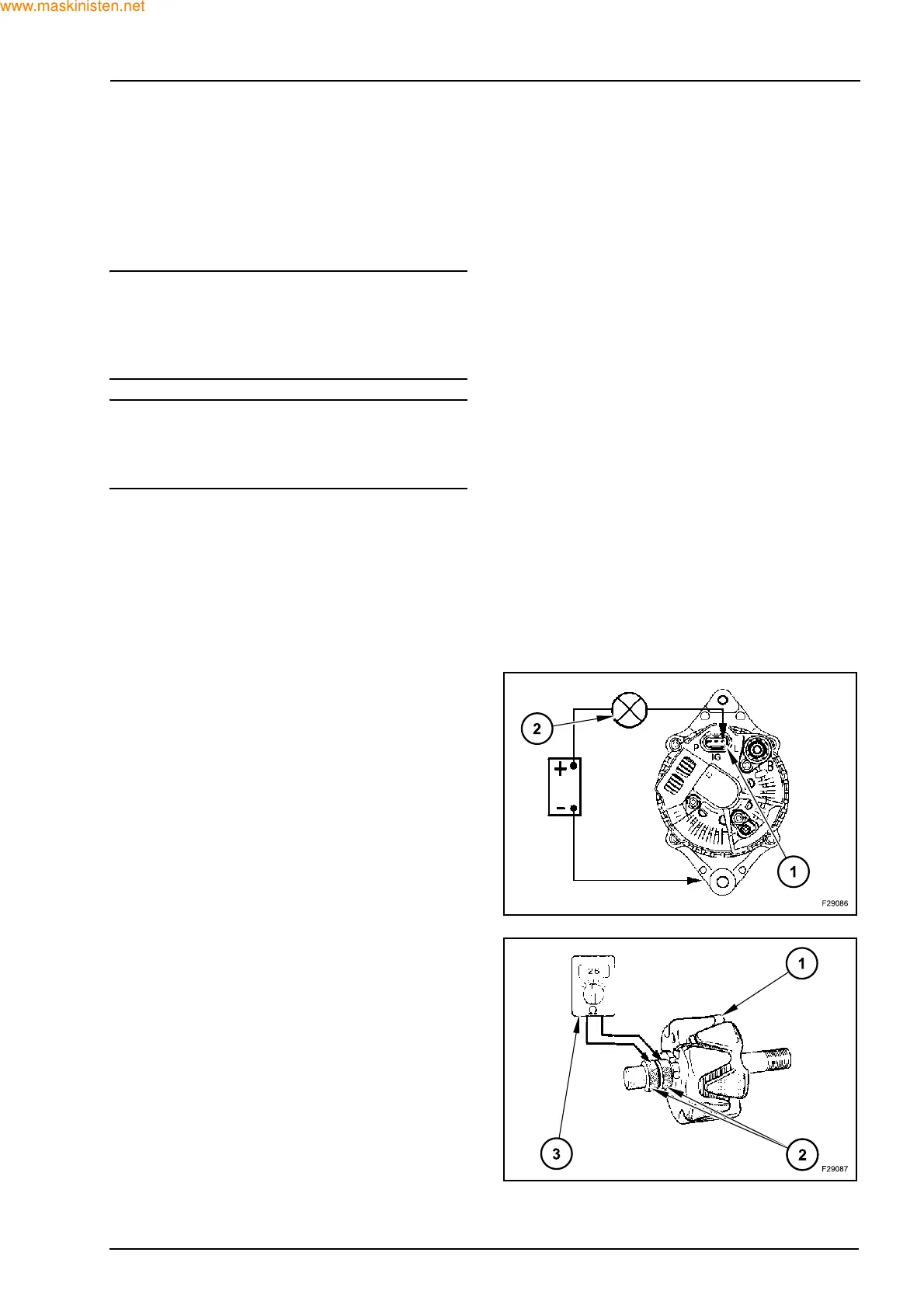
Z Connect a 12 V battery and a 2.2 W test lamp (2) in
series between terminal L (1) and the alternator
body (negative side on body).
Z The test lamp must turn on.
If the lamp does not turn on, the rotor circuit is defec-
tive. Check the brushes, the slip rings and the conti-
nuity of the rotor field windings.
If the inspection reveals that these components are
in good condition, the defect may be due to the reg-
ulator.
CHECKING THE CONTINUITY OF THE ROTOR
FIELD WINDING
Z Remove the regulator with the brush holder.
Z Connect an ohmmeter (3) between the two slip
rings (2). The resistance must be 2.6 ohms at
20 °C.
If the resistance is not correct, replace the rotor (1)
as described in the “Removal” section below.
 Loading...


