EasyManua.ls Logo

CG VSR239p5 - User Manual

Default Icon
180 pages
Print Icon
To Next Page IconTo Next Page
Loading...
Smart solutions.
Strong relationships.
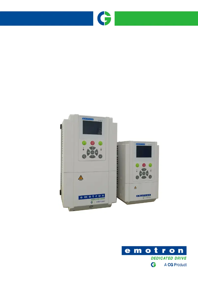
Emotron
VS Series Drive

Table of Contents

Questions and Answers

  • L
    lspencerAug 29, 2025
    What to do if my CG VSR239p5 show Err05?
    • K
      Kevin HallAug 29, 2025
      If your CG DC Drives are showing Err05, consider these potential causes: * The input voltage is too high: Adjust the voltage to normal range. * An external force drives the motor during deceleration: Cancel the external force or install the braking resistor. * The deceleration time is too short: Increase the deceleration time. * The braking unit and braking resistor are not installed: Install the braking unit and braking resistor.
  • J
    Jonathan SmithAug 28, 2025
    What to do if my CG VSR239p5 show Err04?
    • K
      Karen CampbellAug 28, 2025
      If you're seeing Err04 on your CG DC Drives, here's what might be happening: * The input voltage is too high: Adjust the voltage to normal range. * An external force drives the motor during acceleration: Cancel the external force or install a braking resistor. * The acceleration time is too short: Increase the acceleration time. * The braking unit and braking resistor are not installed: Install the braking unit and braking resistor.
  • N
    Nathaniel FowlerAug 27, 2025
    What to do if my CG VSR239p5 DC Drives show Err03?
    • S
      Stacy WhiteAug 27, 2025
      If your CG DC Drives display Err03, it may be caused by: * The output circuit being grounded or short-circuited: Eliminate external faults. * The voltage is too low: Adjust the voltage to normal range. * A sudden load is added during operation: Remove the added load. * The AC drive model is of too small power class: Select an AC drive of higher power class.
  • T
    Tanner BurtonAug 27, 2025
    What to do if my CG VSR239p5 show Err30?
    • N
      ncampbellAug 27, 2025
      If your CG DC Drive shows Err30, consider the following potential causes and solutions: 1. Input voltage is too high: Adjust the voltage to the normal range. 2. There is external force dragging the motor to run in the deceleration process: Cancel external force or install a brake resistor. 3. The deceleration time is too short: Increase the deceleration time. 4. No installation of braking resistor: Install braking resistor.
  • M
    Michael HernandezAug 25, 2025
    What to do if my CG VSR239p5 show Err02?
    • B
      berryjaimeAug 26, 2025
      If your CG DC Drives display Err02, it could be due to: * The output circuit being grounded or short-circuited: Eliminate external faults. * The deceleration time is too short: Increase the deceleration time. * The voltage is too low: Adjust the voltage to normal range. * A sudden load is added during deceleration: Remove the added load. * The braking unit and braking resistor are not installed: Install the braking unit and braking resistor.
  • K
    Katie DavisAug 25, 2025
    What to do if my CG VSR239p5 DC Drives show Err29?
    • E
      ericaayalaAug 25, 2025
      If your CG DC Drive displays Err29, it indicates a fault that can arise from several causes. Here's what you should check: 1. The inverter output circuit is grounded or short-circuited: Troubleshoot peripheral problems. 2. The acceleration and deceleration time is too short: Increase the acceleration time. 3. Manual torque boost or V/F curve is not appropriate: Adjust the manually torque boost or V/F curve. 4. Voltage too low: Adjust the voltage to normal range. 5. Starting the running motor: Select RPM track start or start after the motor has stopped. 6. Sudden load in the acceleration process: Cancel the sudden load. 7. Model selection of inverter power is too small: Select an inverter with a higher rating.

Summary

Chapter 1 Safety Precautions

1.1 Safety Considerations

Essential safety guidelines for using the inverter, covering installation and handling precautions.

1.2 Precautions

Detailed warnings and precautions for motor insulation, thermal protection, vibrations, and electrical safety.

Chapter 3 Installation and Wiring

3.5 Wiring Way of VS Series

Diagrams and descriptions for connecting power and control circuits for various VS series models.

3.6 Terminal Configuration

Detailed breakdown of main and control circuit terminals for different VSX, VSM, VSS, and VSR models.

Chapter 4 Operation and Display

4.1 Introduction of LCD Keypad

Overview of the LCD keypad's appearance, keys, indicators, and parameter setting procedures.

4.2 Introduction of LED Keypad

Explanation of the LED keypad's layout, keys, indicators, and operational functions.

Chapter 5 List of Parameter

5.2 Standard Function Parameters

A detailed list of standard function parameters, their ranges, defaults, and attributes.

Chapter 6 Specification of Parameters

Group b0 Frequency Command

Parameters for controlling the frequency command source and setting operational frequencies.

Group b1 Start;Stop Control Start;Stop Control

Parameters for managing the inverter's start, stop, and running direction control.

Group b2 Accel;Decel Parameters

Parameters for configuring acceleration and deceleration times and curves for motor control.

Group C0 Digital Input

Configuration of digital input terminals for various control functions and signal logic.

Group C1 Digital Output

Definition of functions for digital output terminals like Y1, Y2, and relay outputs.

Group C2 Analog and Pulse Input

Configuration of analog and pulse input terminals, including curve settings and filtering.

Chapter 7 Solar Commissioning

Chapter 8 Elevator Commissioning

Chapter 9 Maintenance and Troubleshooting

Appendix B: Braking Resistor

CG VSR239p5 Specifications

General IconGeneral
BrandCG
ModelVSR239p5
CategoryDC Drives
LanguageEnglish

Related product manuals