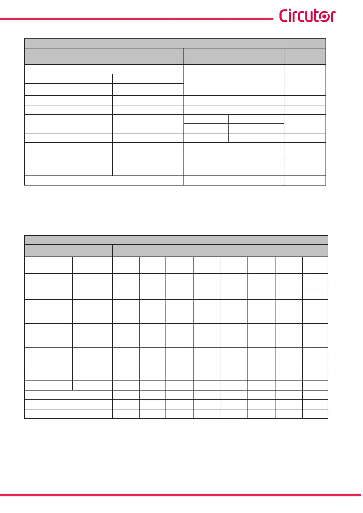
Table 105: Modbus memory map: Transistor digital outputs, expansion modules (Table 1)�
Conguration of Transistor Digital Outputs
Configuration variable
Valid data window Default
value
Variable code Table 32 and Table 33 0
Alarm Impulse output
0 to 100% 0
Pre-alarm value -
Minimum value
(80) -
Table 61 0
Maximum value
(80)
Energy meter factor Table 61 0
Connection delay (ON) High period
(81)
Alarm Impulse output
0
0 to 999 s. 1 to 65536
Disconnection delay (OFF)
Low period
(81)
0 to 999 s. 1 to 65536 0
Latch -
0 : Unlocked
1: Locked
0
Output status -
0 : Normally open
1: Normally closed
0
Module no.
0
0
(80)
When programming the maximum and minimum values, the decimals for the variable selected must be includ-
ed.
(81)
The programmed value is a multiple of 10 ms, when programming 1 the impulse will be at its minimum value
of 10 ms.
Table 106: Modbus memory map: Transistor digital outputs, expansion modules (Table 2)�
Transistor Digital Outputs conguration: Slot 1
Configuration variable
Address
Alarm
Impulse
output
Output
1
Output
2
Output
3
Output
4
Output
5
Output
6
Output
7
Output
8
Maximum value
Energy
meter factor
C350 C364 C378 C38C C3A0 C3B4 C3C8 C3DC
Minimum value -
C352 C366 C37A C38E C3A2 C3B6 C3CA C3DE
Delay in the
Connection
(ON)
High period CE54 C368 C37C C390 C3A4 C3B8 C3CC C3E0
Delay in the
Disconnection
(OFF)
Low period C355 C369 C37D C391 C3A5 C3B9 C3CD C3E1
Value of
Pre-alarm
- C356 C36A C37E C392 C3A6 C3BA C3CE C3E2
Status of
The output
- C357 C36B C37F C393 C3A7 C3BB C3CF C3E3
Latch - C358 C36C C380 C394 C3A8 C3BC C3D0 C3E4
Not used C359 C36D C381 C395 C3A9 C3BD C3D1 C3E5
Variable code
C35A C36E C382 C396 C3AA C3BE C3D2 C3E6
Module no.
C35B C36F C383 C397 C3AB C3BF C3D3 C3E7
Note: The 12 registers must be written and read at once (as a group), otherwise it will respond
with an error.
283
Instruction Manual
CVM-A1000 - CVM-A1500