9-4
Cisco 1240 Connected Grid Router Hardware Installation Guide
OL-26223-04
Chapter 9 Connected Grid Modules
Installing Modules in the Router
Step 3 Use the screwdriver to remove the faceplate that covers the empty module slot.
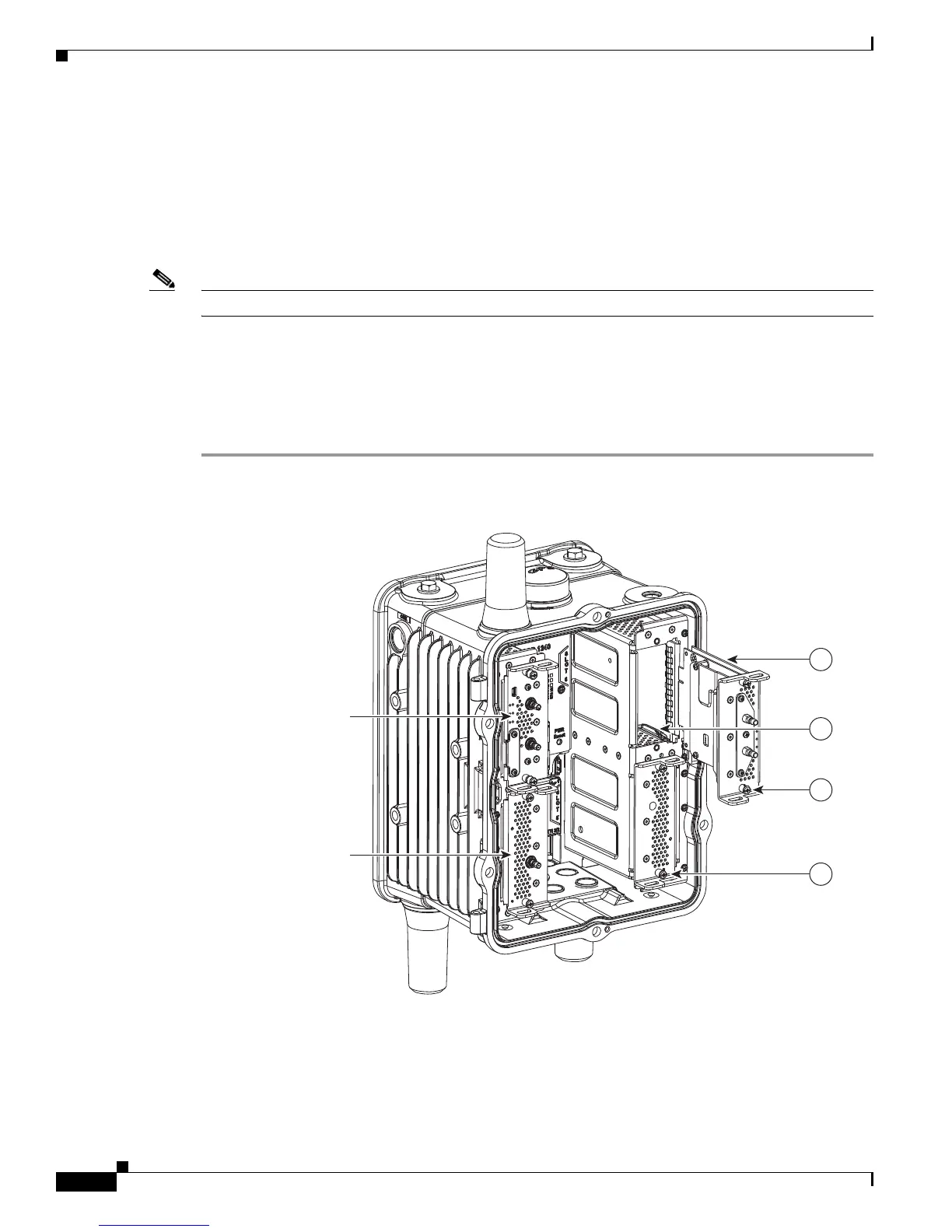
Step 4 Align the module edge with the slot edge guide and insert the module in the router module slot until fully
seated in the connector. (See Figure 9-1.)
Step 5 Use the screwdriver to tighten the captive module mounting screws (two per module) into the connectors
on the router front panel. Torque to 10 to 12 inch-pounds.
Step 6 Attach any required cables to the module. This step is specific to the module type.
Note Refer to the installation and configuration guide for the module, at www.cisco.com/go/cg-modules.
Step 7 Close the router door, following the steps in the “Opening the Router Chassis” chapter.
Step 8 Connect the router to AC power and to the network, following the steps in the “Installing the Router”
chapter.
Step 9 Re-enable the BBU using the commands in the Related Commands section of the “Installing Battery
Backup Units” chapter.
Figure 9-1 Insert Modules into Router
Slot 6 - WiMAX Module
Slot 3 - 3G Module
Slot 4 - WPAN Module
300696
1
2
4
3