14-6
Cisco 1240 Connected Grid Router Hardware Installation Guide
OL-26223-04
Chapter 14 Router LED Locations and States
LED Locations and State Descriptions
Battery Backup Unit LED
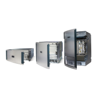
The router supports up to three battery backup units (BBUs). When two or more BBUs are installed, they
are connected to each other in a head-to-tail configuration in the router and the BBU LED are in the
locations shown in Figure 14-3.
To see the LED for each BBU, open the router chassis according to the “Opening the Router Chassis”
chapter.
Figure 14-3 Battery Backup LED Location
LED Color and State Description
BBU (no label) Green solid Idle state
Green blinking Charging
Amber blinking Discharging (providing power to the system)
Amber slow blinking Disabled with the system software
Alternate Red/green blinking Initializing
Red blinking Bootloader mode
Red slow blinking Test mode
Red solid BBU failure
Off Disconnected from router or completely
discharged