3-11
Cisco 1240 Connected Grid Router Hardware Installation Guide
OL-26223-04
Chapter 3 Router Hardware Description
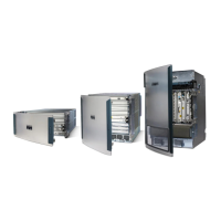
Router Overview
Table 3-8 Interior (Front Panel) Features
Label Description
1 ALARM Connect this alarm port to an alarm system to monitor system errors and events. For
more information, see the “Alarm Port” section on page 3-18.
2 SLOT 3, SLOT4,
SLOT 5, SLOT 6
Install Cisco Connected Grid modules in these four module slots. For more
information, see the “Module Slots” section on page 3-19 and the “Module
Installation Locations” section on page 9-3.
3 ETH 2/3, ETH 2/4,
ETH 2/5, ETH 2/6
Make 10/100 Mbps Ethernet network connections using these four Fast Ethernet
ports. For more information, see the “Fast Ethernet Ports” section on page 3-22.
4 CONFIG Reset Press the CONFIG Reset button to reset the router to the default software
configuration. For more information and a Caution on using this feature, see the
“Reset Buttons” section on page 3-20.
5 IRIG_B Connect the IRIG-B timing port (time source: router—see the “GPS Module” section
on page 3-32) to any device that requires precise time. For more information, see the
“IRIG-B Timing Port” section on page 3-29.
6 ETH 2/1, ETH 2/2 Make 100/1000 Mbps Ethernet network connections using these two Gigabit Ethernet
ports. For more information, see the “Gigabit Ethernet Ports” section on page 3-23.
These physical ports share the ETH 2/1 and ETH 2/2 interfaces with the SFP ports, as
described in the “Combo Ports” section on page 3-25.
7 SER 1/1, SER 1/2 Connect the router to legacy devices, such as RTUs, using these two serial ports. For
more information on these ports and supported devices, see the “Serial Ports” section
on page 3-27.
8 ETH 2/1, ETH 2/2 Install supported small form factor pluggable (SFP) modules in these two SFP ports.
For more information and supported SFPs, see the “Small Form-Factor Pluggable
(SFP) Ports” section on page 3-24. These physical ports share the ETH 2/1 and
ETH 2/2 interfaces with the 100/1000 Mbps ports, as described in the “Combo Ports”
section on page 3-25.
9 – The LEDs indicate alarm port status and connection status for Ethernet, WiFi, and
GPS connections. The LED label is located in the center of the chassis (see
Figure 3-8). For more information, see the “Router LED Locations and States”
chapter.
10 – The door alarm switch triggers the router to generate a syslog event and send an SNMP
alarm when the door is opened. For more information on physical security features of
the router chassis, see the “Opening the Router Chassis” chapter.
11 PWR RESET Press the PWR RESET button to power cycle the router. For more information on
using this feature, see the “Reset Buttons” section on page 3-20.
12
Connect these USB ports to supported, external USB devices. For more information,
see the “USB Ports” section on page 3-30.
13 – Use the external Fast Ethernet connector to connect the router to an Ethernet network
without requiring access to the router interior. This port is connected to one of the
router internal FE ports. For more information, see the “Installing the Router” chapter.