12-10
Catalyst 2960 and 2960-S Switches Software Configuration Guide, Release 15.0(1)SE
OL-26520-01
Chapter 12 Configuring Interface Characteristics
Understanding Interface Types
PoE port, the switch does not police the real-time power consumption of the device, and the device can
consume more power than the maximum allocated amount, which could adversely affect the switch and
the devices connected to the other PoE ports.
Because the switch supports internal power supplies and the Cisco Redundant Power System 2300 (also
referred to as the RPS 2300), the total amount of power available for the powered devices varies
depending on the power supply configuration.
• If a power supply is removed and replaced by a new power supply with less power and the switch
does not have enough power for the powered devices, the switch denies power to the PoE ports that
are in auto mode in descending order of the port numbers. If the switch still does not have enough
power, it denies power to the PoE ports in static mode in descending order of the port numbers.
• If the new power supply supports more power than the previous one and the switch now has more
power available, the switch grants power to the PoE ports in static mode in ascending order of the
port numbers. If it still has power available, the switch then grants power to the PoE ports in auto
mode in ascending order of the port numbers.
For configuration information, see the “Configuring Power Policing” section on page 12-36.
PoE Uplinks and PoE Pass-Through Capability
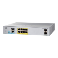
The Catalyst 2960-C compact switch can receive power on the two uplink Gigabit Ethernet ports from
a PoE or PoE+ capable-switch (for example a Catalyst 3750-X or 3560-X switch). The switch can also
receive power from an AC power source when you use the auxiliary power input. When both uplink ports
and auxiliary power are connected, the auxiliary power input takes precedence.
The Catalyst 2960CPD-8PT switch can provide power to end devices through the eight downlink ports
in one of two ways:
• When the switch receives power from the auxiliary power input, it acts like any other PoE switch
and can supply power to end devices connected to the eight downlink ports according to the total
power budget. Possible end devices are IP phones, video cameras, and access points.
• When the switch receives power through one or both uplink ports, it can provide PoE pass-through,
taking the surplus power from the PoE or PoE+ uplinks and passing it through the downlink ports
to end devices. The available power depends on the power drawn from the uplink ports and varies,
depending if one or both uplink ports are connected and if the source is PoE or PoE+.
The downlink ports are PoE-capable, and each port can supply up to 15.4 W per port to a connected
powered device. When the switch draws power from the uplink ports, the power budget (the available
power on downlink ports) depends on the power source options shown in the table. When the switch
receives power through the auxiliary connector, the power budget is similar to that of any other PoE
switch.
Table 12-2 Catalyst 2960CPD-8PT Power Budget
Power Source Options Power Sent from Uplink Switches Available PoE Budget
1 PoE uplink port 15.4 W 0
2 PoE uplink ports 30.8 W 7 W
1 PoE+ uplink port 30 W 7 W
1 PoE and 1 PoE+ uplink 45.4 W 15.4 W
2 PoE+ uplink ports 60 W 22.4 W
Auxiliary power input — 22.4 W

 Loading...


