16-4
Catalyst 2960 and 2960-S Switches Software Configuration Guide, Release 15.0(1)SE
OL-26520-01
Chapter 16 Configuring STP
Understanding Spanning-Tree Features
–
Selects the lowest designated bridge ID
–
Selects the lowest designated path cost
–
Selects the lowest port ID
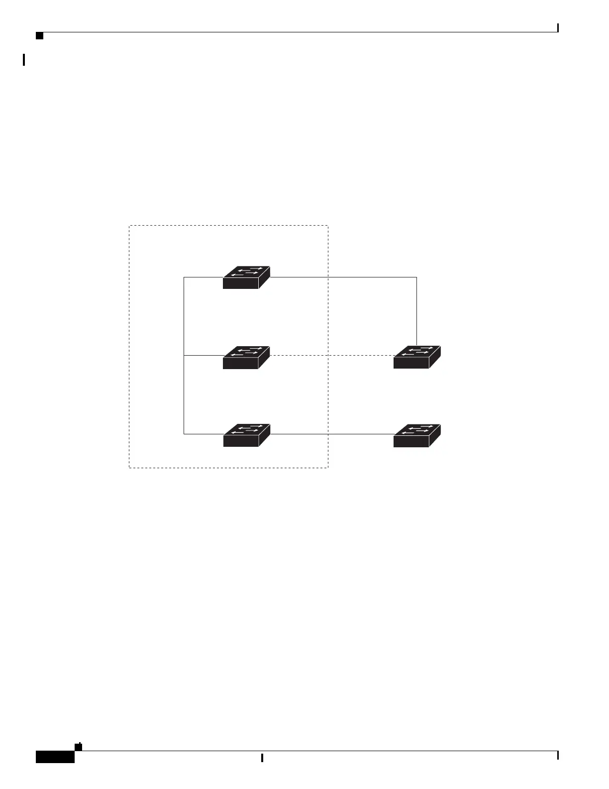
Only one outgoing port on the stack root switch is selected as the root port. The remaining switches
in the stack become its designated switches (Switch 2 and Switch 3).
• The shortest distance to the root switch is calculated for each switch based on the path cost.
• A designated switch for each LAN segment is selected. The designated switch incurs the lowest path
cost when forwarding packets from that LAN to the root switch. The port through which the
designated switch is attached to the LAN is called the designated port.
All paths that are not needed to reach the root switch from anywhere in the switched network are placed
in the spanning-tree blocking mode.
Bridge ID, Switch Priority, and Extended System ID
The IEEE 802.1D standard requires that each switch has an unique bridge identifier (bridge ID), which
controls the selection of the root switch. Because each VLAN is considered as a different logical bridge
with PVST+ and rapid PVST+, the same switch must have a different bridge IDs for each configured
VLAN. Each VLAN on the switch has a unique 8-byte bridge ID. The 2 most-significant bytes are used
for the switch priority, and the remaining 6 bytes are derived from the switch MAC address.
Switch 1
Catalyst 2975 switch stack
DP Outgoing RP
Switch 2
RPStack port
connections
BP
DP
Switch 3
Switch A
Switch B
RP
DP
Spanning-tree root
RPDP
RP = root port
DP = designated port
BP = blocked port
250866