000 299 119 5 - BA ROLLANT 240 - 250 - 254 - 255 7.3.1
Prior to operation
ELECTRICAL SYSTEMS
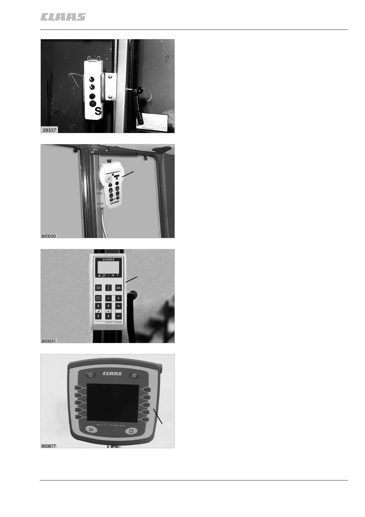
Control box
Standard operation
Attach the mounting support supplied onto the tractor
at a position within reach of the driver.
For ROLLANT 240/250, insert control box (S) in the
bracket, for ROLLANT 254/255, insert control box (T)
in the bracket.
(Fig. 1, 2)
Control Terminal
Attach the mounting support supplied onto the tractor
at a position within reach of the driver.
As an option for ROLLANT 254/255, insert Control
Terminal (V) in the bracket
(Fig. 3)
Claas Communicator
Attach the bracket supplied for Claas Communicator
(B) to the tractor within the reach and vision of the
driver.
Insert the Claas Communicator into the bracket and
tighten wing nut.
(Fig. 4, 5)
1
T
2
V
3
B
4
Prior to operation

 Loading...