Group 19, Motor Controls
SM 765, Sep ’06 Control Programming • 19-2-17
TESTER MENU
The most important input or output signals can be measured in real time using the TESTER function of the handset. The
handset acts as a multimeter able to read voltage, current and temperature. The following is a list of measurements for
different configurations.
Handset Tester: user can verify the state of the following parameters:
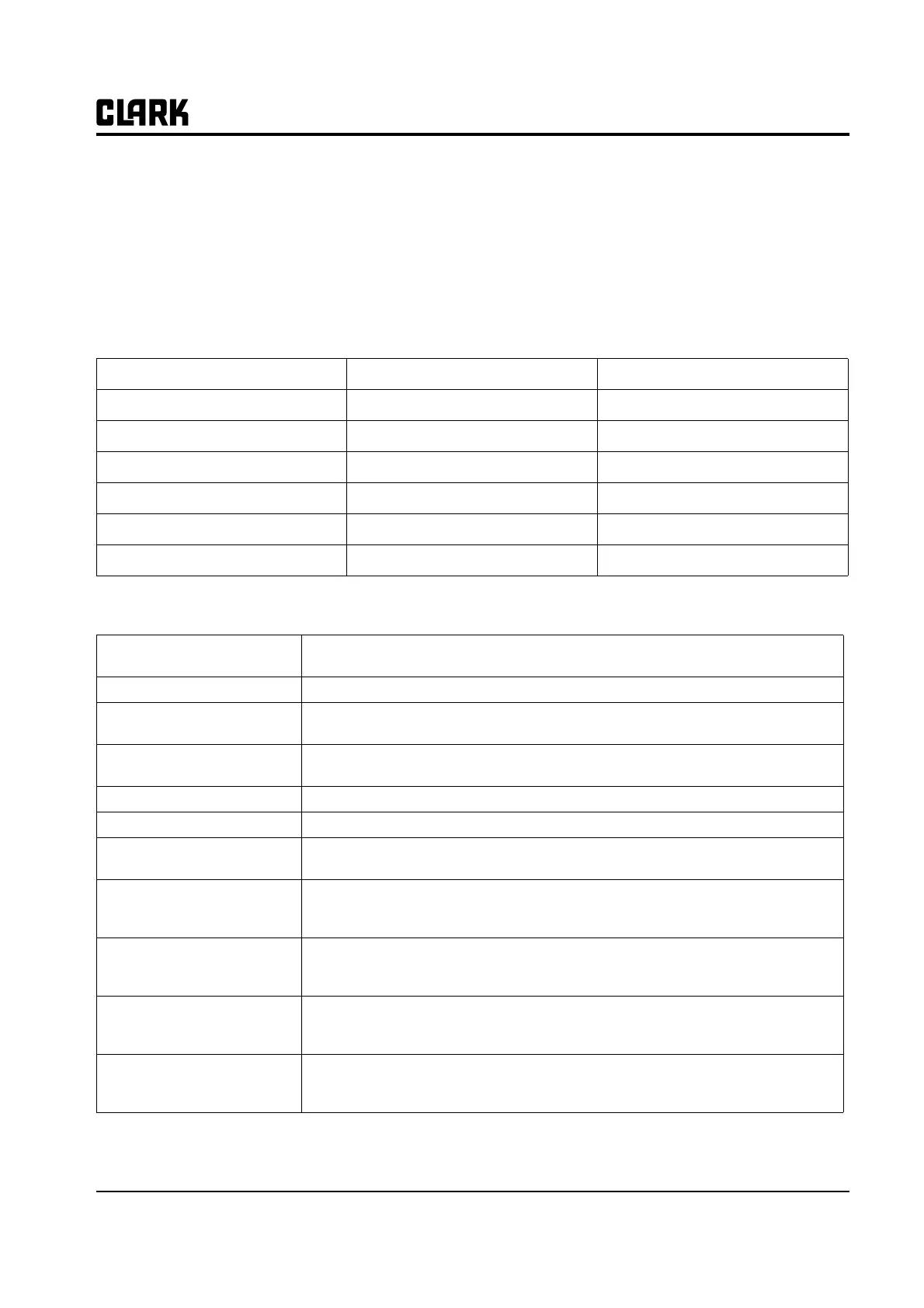
PUMP CONTROL
Motor voltage (%) Accelerator (V) Hydro speed req. (ON/OFF)
Frequency (Hz) Lifting switch (ON/OFF) Voltage booster (%)
Encoder (Hz) 1st speed switch (ON/OFF) Battery voltage (V)
Slip Value (Hz) 2nd speed switch (ON/OFF) Cos fi
Current RMS (A) 3rd speed switch (ON/OFF) Battery Current (A)
Temperature (°C) 4th speed switch (ON/OFF) Battery charge (%)
Motor Temperature (°C)
1) MOTOR VOLTAGE: This is the voltage supplied to the motor by the controller; it is expressed as a percent-
age of full battery voltage.
2) FREQUENCY: This is the frequency of the voltage and current supplied to the motor.
3) ENCODER: This is the speed of the motor, expressed in the same unit of the frequency; this infor-
mation comes from the speed sensor.
4) SLIP VALUE: This is the difference of speed between the rotating field and the shaft of the motor,
expressed in the same unit of the frequency.
5) CURRENT RMS: Root Mean Square value of the motor current.
6) TEMPERATURE: The temperature measured on the aluminum heat sink holding the MOSFET devices.
7) MOTOR TEMPERATURE: This is the temperature of the right motor; if this option is programmed "None" it
shows 0°.
8) ACCELERATOR: The voltage of the accelerator potentiometer's wiper (CPOT). The voltage level is
shown on the left-hand side of the console display and the value is in percentage is
shown on the right-hand side
9) LIFTING SWITCH: Status of lifting switch.
ON /+BV = input active, switch closed.
OFF / GND = input non-active, switch open.
10) TILT SPEED SWITCH:
ON /+BV = input active, switch closed.
OFF / GND = input non-active, switch open.
11) AUX1 SPEED SWITCH:
ON /+BV = input active, switch closed.
OFF / GND = input non-active, switch open.