Group 25, Steering Column and Gear
25-3-2 • Steering Column and Component Removal and Replacement SM 765, Dec ’06
1. Park truck on a hard, level, and solid
surface, such as a concrete floor with no
gaps or breaks.
2. Put upright in vertical position and fully
lower the forks or attachment.
3. Put all controls in neutral. Turn key
switch OFF and remove key.
4. Apply the parking brake and block the
wheels.
Steering Column and Component
Removal
Determine which component requires service and check
the procedure for removing that component. Read the pro-
cedure completely before beginning disassembly.
Hand Wheel, Light Switch Lever, and
Directional Control Assembly Removal
1. Disconnect the battery.
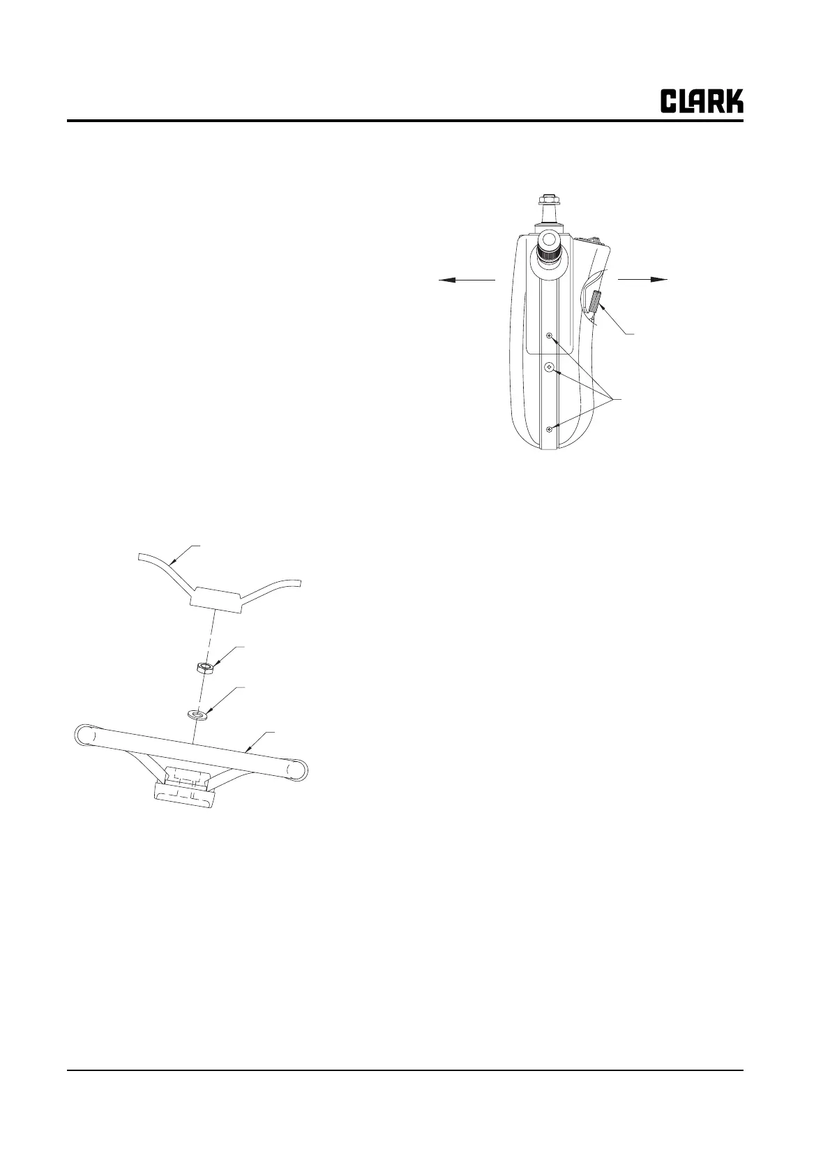
2. Remove a hand cover and release nut and washer
securing handle to steering column.
3. Remove 8 screws secruing both column cover using
(+) driver. Disconnect connector assembled on locker
switch and pull rear cover smoothly after removing
tilt lock leveler.
N
TE
Use care when removing the backside cover
as the rocker switch wiring is attached.
4. Disconnect wire connector assembled to direciton
control lever and light switch lever and remove direc-
tion control lever and light switch lever from steering
column by releasing two (+) screw.
Column Tilt Lock Assembly Removal
N
TE
The tilt lock assembly is not serviceable; only
the gas springs are serviceable. The tilt lock
assembly should be removed only for replace-
ment as a complete assembly.
1. Remove the negative cable of battery.
2. Refer to "Handle, light switch lever and direction
control assembly removal" to remove upper cover.
3. Use (+) drive to remove 4 screws secruing lower col-
umn lever and then lower cover.
Steer Handle Cover
Steer Handle Screw
Steer Handle Washer
Steer Handle
Tilt Lock Lever
Cover Screw