Group 32, Tilt Cylinders
SM 765, Nov ’06 Tilt Cylinder Removal and Replacement • 32-3-3
6. Remove lock-plate from tilt cylinder rod-end yoke.
Use a soft drift and hammer to tap rod-end pin out of
yoke.
7. Pop the cover from tilt cylinder base access port on
the step to the operator’s compartment.
8. Remove the lock-plate from cylinder base yoke. Use
a soft drift and hammer to tap pin out of yoke.
9. Remove cylinder assembly.
Parts Inspection
1. Clean all bearings, pins, and other components in an
approved cleaning fluid.
2. Inspect all parts for scratches, nicks, dents, and wear.
Check the cylinder rods to be sure they are smooth
with no scratches. Check all threaded parts for dam-
age.
3. Replace all parts which show damage.
4. If parts are to be left exposed, coat all mating sur-
faces of parts with a light layer of engine oil.
Tilt Cylinder Replacement
1. Position tilt cylinder base yoke on frame mounting
bracket.
2. Insert base pin in cylinder base yoke and through
frame mounting bracket, making sure slot in pin is in
line with the lock-plate. Grease fitting must point
toward center of truck.
IMP
RTANT
Make sure the spherical bearing is aligned so
that pin fits smoothly in yoke.
3. Install base pin lock-plate in slot and fasten to yoke
with fastener. Tighten fastener to a torque of 40-45
N⋅m (30-33 ft-lb).
4. Position rod-end yoke on upright mounting bracket
and insert rod-end pin, making sure lock-plate slot is
in correct position. Grease fitting must be toward
center of truck. Make sure the spherical bearing is
aligned so that pin fits smoothly in yoke.
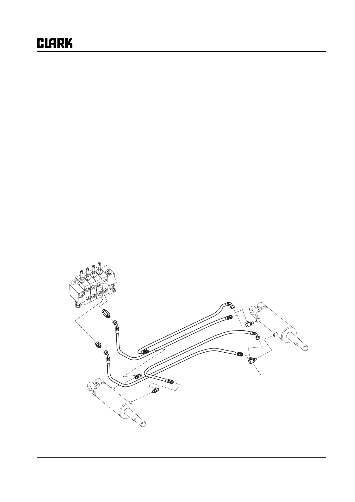
Till Cylinder Hydraulic Fittings
Tee Fitting