Group 34, Uprights
SM 765, Nov ’06
Carriage and Upright Roller Clearance Checks and Shim Adjustments
• 34-4-5
Upright Rollers
1. Remove the carriage as described in Section 7 of this
Group.
2. Fully extend the upright making sure carriage hoses
and chains are secured out of the way to prevent
damage.
WARNING
!
An upright or carriage can move unexpect-
edly:
• Do not walk or stand under raised forks
• Keep clear of load and carriage when
making any check or adjustment
• Keep your arms and fingers away from
moving parts of the upright.
• Do not reach through open areas of the
upright.
• Never attempt to move or align the rails
by hand. Use a prybar.
• Use an approved safety platform to reach
the upper areas of the upright. Never use
the upright as a ladder.
Failure to follow these warnings can result in
serious injury.
3. Follow the “General Roller Side Clearance Checking
Procedure” given earlier in this Section.
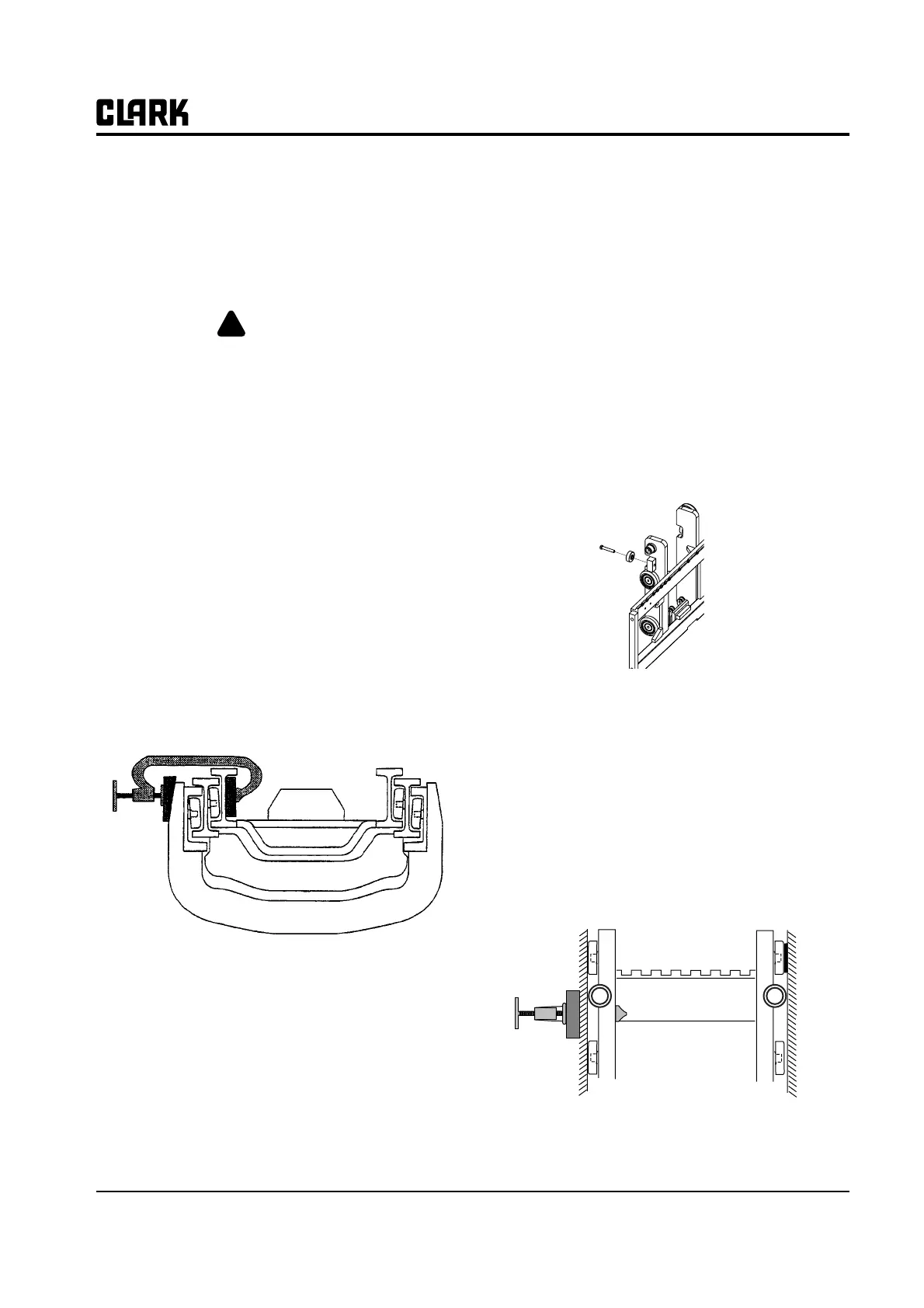
The clamping procedure is as illustrated below.
Internal Thrust Roller Adjustment
The internal thrust rollers should be adjusted to extend 0-
0.75 mm (0.03 in) into the top carriage roller side clear-
ance. Carriage roller side clearance should be within toler-
ances before you adjust the thrust rollers.
N
TE
Carriage must be replaced on upright before
adjusting internal thrust rollers. See Section
8 for carriage replacement procedures.
1. Lift the carriage to the top of the inner rail.
2. Loosen the jam nut on the back of the thrust roller
cap screw and then loosen the cap screw. Rotate the
bearing to pivot toward the carriage and away from
the rail.
3. Lower the carriage to a convenient height to do the
adjustment.
4. Clamp the carriage between the top and middle car-
riage roller.
• Use a shim block under the clamp on the outside of
the channel rail.
• Torque on the clamp should not exceed 25 N⋅m (20
ft-lb).
5. Insert a 0.5 mm (0.02 in) temporary shim between
the top carriage roller and the rail web on the side
opposite the clamp. If a 0.5 mm (0.02 in) shim will
not fit, insert a 0.25 mm (0.01 in) shim.