Group 34, Uprights
34-4-4 •
Carriage and Upright Roller Clearance Checks and Shim Adjustments
SM 765, Nov ’06
6. If the clearance at the widest rail set span is more
than 2.25 mm (0.09 in), the roller set needs shim-
ming.
If the clearance at the narrowest rail set span is more
than 1.0 mm (0.04 in), the roller set should be
shimmed; however, it is OK for the middle carriage
roller gap to be up to 1.5 mm (0.06 in).
7. Repeat entire procedure for each roller set, following
the instructions in “Directions for Checking Specific
Rollers” below.
Directions for Checking Specific Rollers
Use these directions to supplement the general procedures
given above.
Carriage Rollers
Bottom Carriage Rollers
Follow the general procedure above.
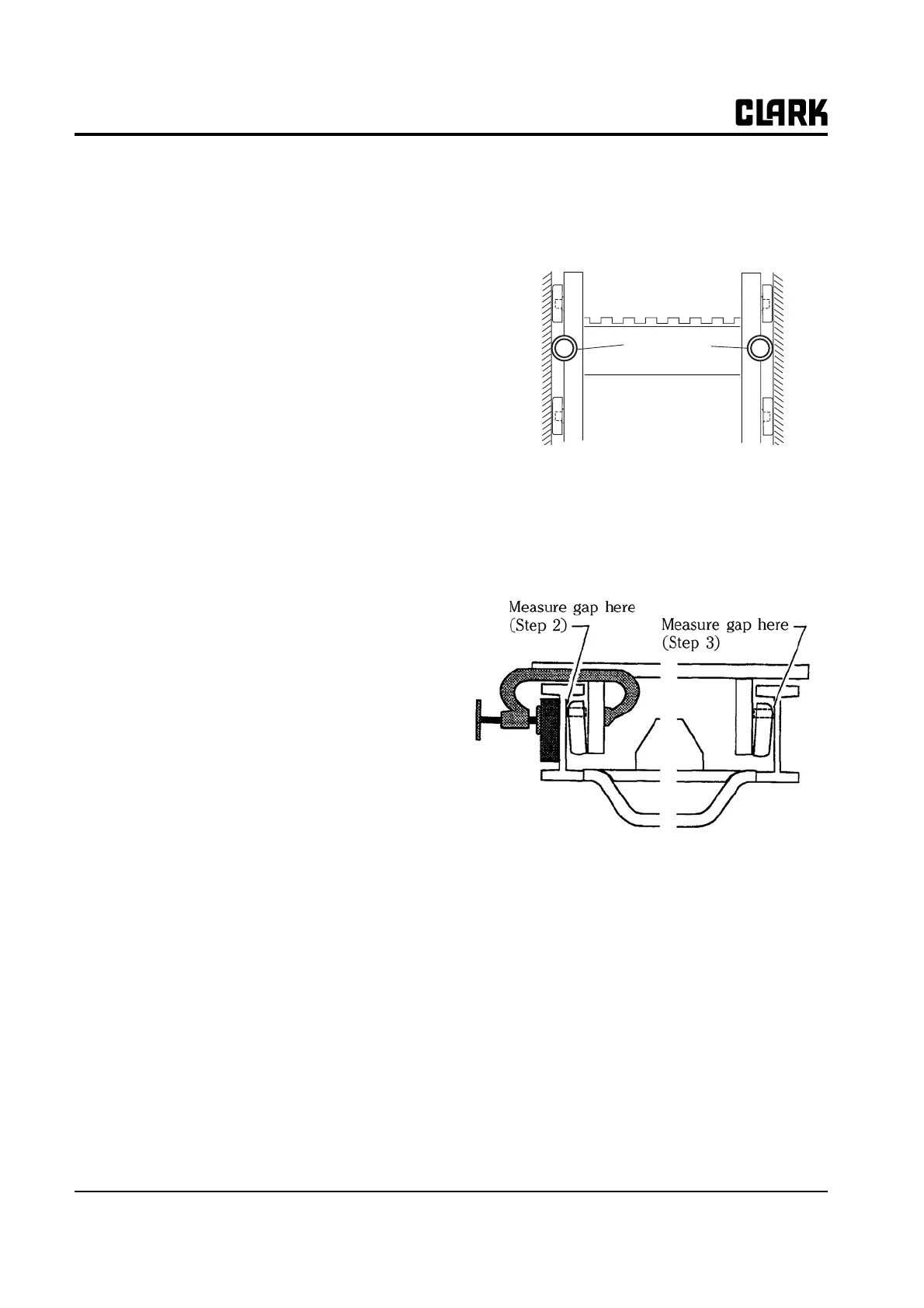
Middle Carriage Rollers
The middle rollers are difficult to access and require the
following special procedures.
1. Raise the carriage until the middle rollers are at the
top of the inner rails.
2. Measure roller side clearance at the top of the inner
rails. Note measurement here:
_____________________.
If gap is less than 1.5 mm (0.06 in), shimming is not
required.
If gap is more than 1.5 mm (0.06 in), check clearance
at narrowest span by comparison with the top of the
rail set as follows:
a. With spanner tool, measure span of inner rail set
at top of the front web area. Note measurement
here: _____________________.
b. With spanner tool, measure span of inner rail set
at narrowest span of front web area. Note mea-
surement here: _____________________.
c. Subtract measurement in step b from measure-
ment in step a, Write result here:
b-a= _____________________.
If the calculated gap is less than or equal to the
gap measured in step 2, the roller set does not
require shimming. Otherwise, the roller set
should be shimmed.
Top Carriage Rollers and Internal Thrust Rollers
The internal thrust rollers are nearly perpendicular to the
top carriage lift rollers and contact the same flange area as
the carriage rollers. The top carriage lift rollers and the
internal thrust rollers should be checked together.
1. Move the top carriage lift roller to the narrowest span
on the inner rails set.
2. Clamp rail to one side as in general procedures.
Check clearance of lift roller on clamped side. Locate
the clamp between the thrust roller and the bottom
roller of the carriage.
The internal thrust roller should contact the web and
cause the lift roller to stand off from the web by .01
to 1 mm (0.001-0.03 in). If the gap is outside this
range, the internal thrust roller must be adjusted as
explained later in this Section under “Internal Thrust
Roller Adjustment.”
3. Check clearance on lift roller opposite clamped side
as in the general procedures. If clearance is greater
than 1.25 mm (0.05 in), the roller set should be
shimmed.
4. Move clamp to opposite side and check clearance on
clamped side as in step 2 directly above. Gap should
be 0.01-1.0 mm (0.001-0.03 in).
5. Move the top carriage lift roller to the widest span on
the inner rail set and check clearance as in general
procedures.
Rollers
Interral Thrust
Rollers