Group 34, Uprights
34-8-4 • Upright Removal and Replacement SM 765, Nov ’06
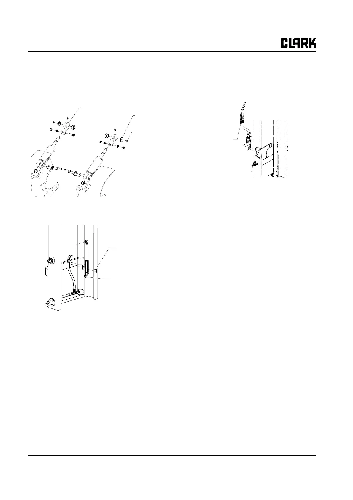
2. Install rod end pins, lock plates, and fasteners.
Tighten lock plate fasteners to a torque of 40-45 N⋅m
(30-33 ft-lb).
3. Attach hydraulic lines to the upright flow control
valve:
• Lubricate all O-rings with a light coating of system
hydraulic fluid or a compatible oil.
• Use two wrenches to tighten hose fittings to pre-
vent twisting lines.
• See Group 40 for hydraulic fitting tightening pro-
cedures.
N
TE
Reconnect two-hose adapter assembly
hydraulic lines to the upright-mounted
bracket.
4. Remove the lift chain between the upright and hoist.
5. Completely check all upright and hydraulic compo-
nents under load before returning the truck to service.
6. See Section 8, “Fork and Carriage Removal and
Replacement,” for steps to replace the carriage and
fork assembly.
Tilt cylinder
Mounting
Tilt cylinder
mounting Bolt
Tilt cylinder
Rod end
Reconnect
line here
Connect the
mounting bolts
to the manifold
Reconnect
lines here