833-3577 CB-FALCON SYSTEM OPERATOR INTERFACE
750-241 33 65-0296—01
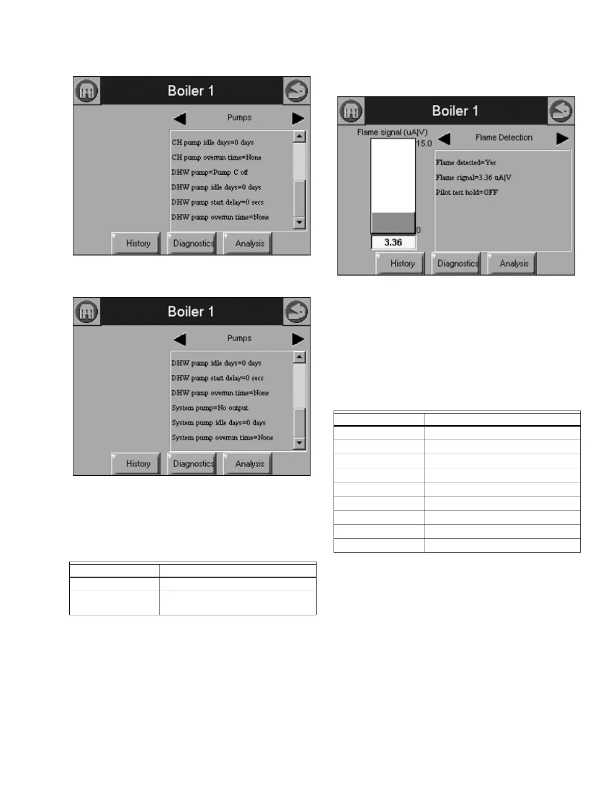
Fig. 76. 833-3639 Pump Status menu (middle).
Fig. 77. 833-3639 Pump Status menu (bottom).
The status data shown in Table 31 is displayed for flame
detection in the 833-3639.
The bar graph displayed for this status is the flame signal.
Fig. 78. Flame Detection Status menu.
NOTE: This same status is also displayed for burner control
status. A separate status group is defined, however,
to provide a bar graph of the flame signal and to
automatically launch a flame signal trend analysis.
Table 32 displays the statistics status page data for the 833-
3639.
The bar graph displayed for this status is the outlet sensor
temperature.
Table 31. Flame Detection Status.
Data Comment
Flame signal V (voltage)
Pilot test hold On or Off (only applicable when pilot
type is interrupted)
Table 32. 833-3639 Statistics Status.
Data Comment
Auxiliary pump cycles Number of cycles
Boiler pump cycles Number of cycles
Burner cycles Number of cycles
Burner run time Duration of run time
CH pump cycles Number of cycles
Controller cycles Number of cycles
Controller run time Duration of run time
DHW pump cycles Number of cycles
System pump cycles Number of cycles