833-3577 CB-FALCON SYSTEM OPERATOR INTERFACE
750-241 35 65-0296—01
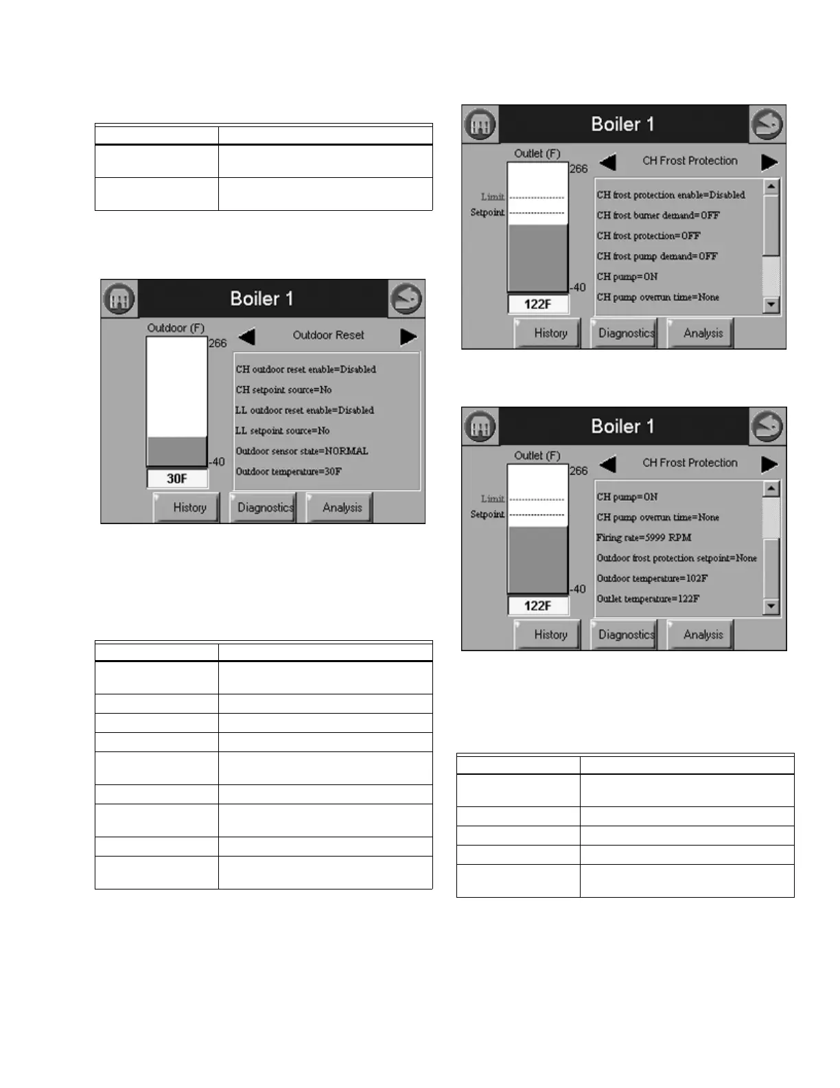
The bar graph displayed for this status is the outdoor sensor
temperature.
Fig. 83. Outdoor Reset Status menu.
Table 36 shows the status page data when Frost protection is
configured for the 833-3639.
The bar graph displayed for this status is the outlet sensor
temperature. Trend analysis displayed for this status is outlet
sensor, outdoor sensor, CH frost, and outdoor frost
temperatures.
Fig. 84. CH Frost Protection Status menu (top).
Fig. 85. CH Frost Protection Status menu (bottom).
Table 37 shows the status page data when Frost protection
and DHW heating are configured for the 833-3639.
The bar graph displayed for this status is the DHW sensor
temperature. Trend analysis displayed for this status is DHW
sensor, outdoor sensor, and DHW frost temperatures.
Table 35. Outdoor Status.
Data Comment
Outdoor temperature Outdoor temperature (same as bar
graph)
Outdoor sensor state None, Monitor, Open, Short, Alarm
(None=no outdoor temp sensor)
Table 36. CH Frost Protection Status.
Data Comment
Frost protection state None, Monitor, Active (frost protection
occurring)
Burner control state Burner control sequence state
Firing rate
Outlet temperature Outlet sensor temperature
CH frost temperature CH temperature when frost protection
becomes active
Outdoor temperature Outdoor temperature (when enabled)
Outdoor frost
temperature
Outdoor temperature when frost
protection becomes active
CH pump On or Off (CH pump switch)
CH pump override Pump override time countdown (poll
every second?)
Table 37. DHW Frost Protection Status.
Data Comment
Frost protection state None, Monitor, Active (frost protection
occurring)
Burner control state Burner control sequence state
Firing rate
DHW temperature DHW sensor temperature
DHW frost
temperature
DHW temperature when frost
protection becomes active