833-3577 CB-FALCON SYSTEM OPERATOR INTERFACE
65-0296—01 36 750-241
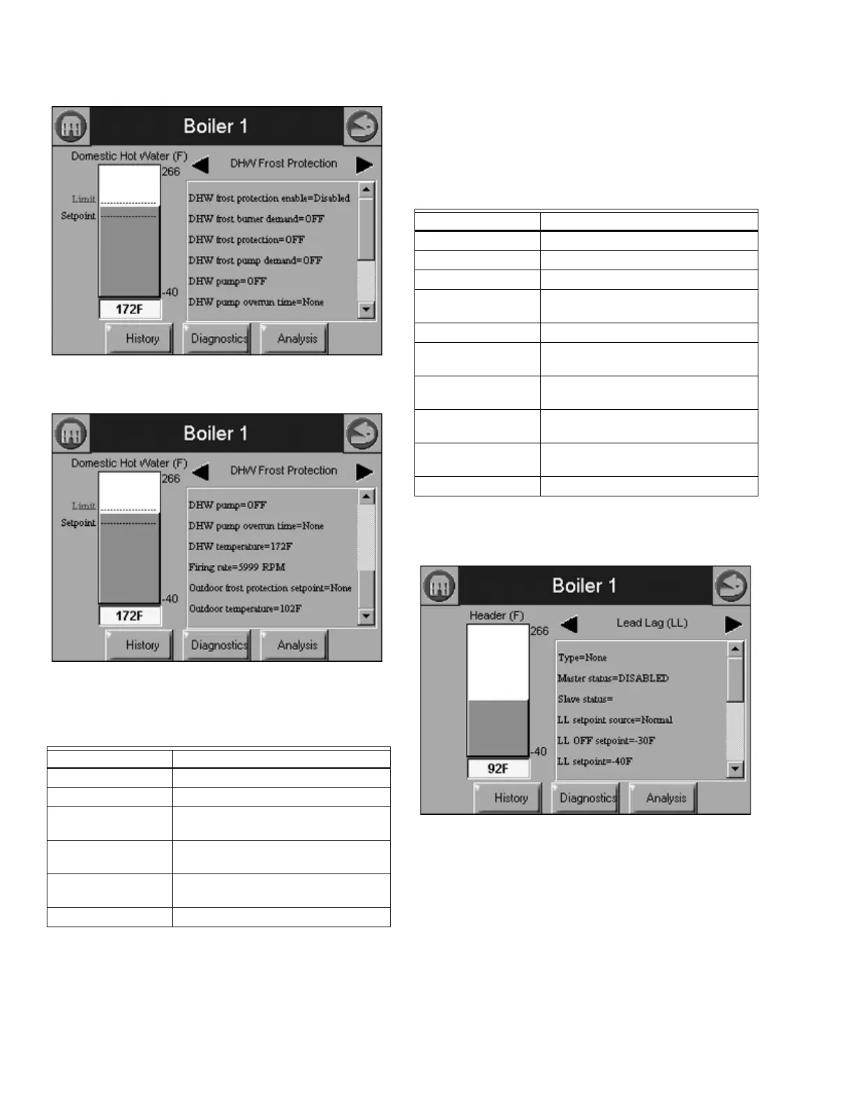
Fig. 86. DHW Frost Protection Status menu (top).
Fig. 87. DHW Frost Protection Status menu (bottom).
Table 36 shows the statistics that are displayed for the 833-
3639.
The bar graph and trend analysis displayed for this status is
the outlet sensor temperature. See Fig. 60.
Table 38 shows the status page data when Lead Lag is
configured for the 833-3639.
The bar graph displayed for this status is the header sensor
temperature.
Fig. 88. Lead Lag Status menu (top).
Data Comment
Burner cycles Burner cycle count
Burner hours Burner runtime hours
CH pump cycles CH pump cycle count (transition from
off to on)
DHW pump cycles DHW pump cycle count (transition
from off to on)
System pump cycles System pump cycle count (transition
from off to on)
Calls for heat
Table 38. Lead Lag Status.
Data Comment
Type Slave, Master, or Master & Slave
Lead Lag status Disabled, Normal, Suspended
Slave status Valid at slave only.
Slave mcrate (master
control rate)
% load of entire system. Set by
master.
System pump On or Off (System pump switch).
System pump
overrun time
Count down of System pump overrun
Staging demand to
modulation delay
Seconds (applicable at master only).
Header temperature Get from master 833-3639 (same as
bar graph)
Header sensor state None, Monitor, Open, Short, Alarm
(None=no header temp sensor)
Lead Lag setpoint Get from master 833-3639.