ProtoNode Gateway
16 750-426
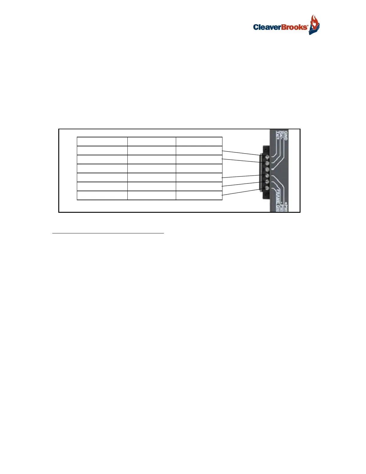
3.2 Device Connections to ProtoNode
ProtoNode 6 Pin Phoenix connector for RS-485 Devices
The 6 pin Phoenix connector is the same for ProtoNode RER (BACnet) and LER (LonWorks).
Pins 1 through 3 are for Modbus RS-485 devices. The RS-485 GND (Pin 3) is not typically con-
nected.
Pins 4 through 6 are for power. Do not connect power (wait until Section 3.6).
FIGURE 10 - RS-485 and Power Connections
3.2.1 Biasing the Modbus RS-485 Network
An RS-485 network with more than one device needs to have biasing to ensure proper communica-
tion. The biasing only needs to be done on one device.
The ProtoNode has 510 Ohm resistors that can be used to set the biasing. The ProtoNode's default
positions from the factory for the biasing jumpers are OFF.
The OFF position is when the 2 RED biasing jumpers straddle the 4 pins closest to the outside of the
board of the ProtoNode. See Figure 11.
Only turn biasing ON:
• IF the BMS cannot see more than one device connected to the ProtoNode
• AND all the settings (Modbus COM settings, wiring, and DIP switches) have been checked.
To turn biasing ON, move the 2 RED biasing jumpers to straddle the 4 pins closest to the inside of
the board of the ProtoNode.
Device Pins ProtoNode Pin # Pin assignment
Pin RS-485 + Pin 1 RS-485 +
Pin RS-485 - Pin 2 RS-485 -
Pin GND Pin 3 RS-485 GND
Power In (+) Pin 4 V +
Power In (-) Pin 5 V -
Frame Ground Pin 6 FRAME GND