11
OWER ATTACHMENT (FOR NON FREE-STANDING UNITS ONLY)
he tower must be fastened to a structurally stable wall with a maximum center size of 24" (610 mm)
nd with the tower tie brackets provided within the tower. (This depends on the model and the travel
eight). Additional instructions on the dimensional drawings show the loads imposed on the structural
all.
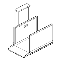
) To attach the tower back to the shaft wall, tie bracket holes can be accessed through the
removable front service panels. The tie brackets at the rear inside of the tower have been
punched with slotted holes. Use anchors for concrete and lag bolts for wood to secure
the tower to a stable support. Some site drilling may be required for proper fastening to
the structural wall. See Figure # 5.
) The lowest tower attachment is at the second tie bracket above the pit channel. See
Figure # 5.
)
When drilling the tie brackets’ holes, cover the electronic components and use
caution when working near them.
NOTE
T
T
a
h
w
1
2
3
This completes the tower fastening procedure for units up to 48" (1220 mm) of travel. For units
traveling higher than 48" (1220 mm), the tower ust be fastened at 24" (610 mm) intervals at m
center.
NEVER OPERATE THE LIFT UNTIL THE TOWER IS
SECURELY FASTENE .
PORTANT NOTES
) Verify that the tower is plumb and square when attached to the structural wall.
) Use the shims behind the tower at each anchor point to prevent distorting the tower, as
required. In some cases, if the wall is not smooth, plumb and square, special shims may
have to be made by t
) Do not pull or twist the tower out-of-square when tightening the fasteners, since this
affects the proper operation of the lift.
) Make sure that the top cap can be removed for access to the internal parts. This is
particularly necessary after the General Contractor has completed his work.
D
IM
A
B
he installer.
C
D