33
HANDILIFT SE (SEMI-ENCLOSED) INSTALLATION
The Handilift SE base unit must be assembled following the mechanical and electrical procedures
previously detailed in this manual.
RE E
For pit and
the installa
1) If there is a pit, then align the pit and make it perpendicular to the hoistway wall. The
support wall must be plumb and smooth.
2) The pit must be 3" (76 mm) in depth. The pit foundation must be level.
3) Ensure that the floor is flat and level.
ASS B
P -D LIVERY
hoistway applications, the following must be checked and verified before proceeding with
tion of the semi-enclosure:
EM LY
NOTE
Before assembling the enclosure panels, it is recommended that all gate wiring should be
brought th ace is restricted once rough the conduit hole provided at the base of the tower. Sp
panels are assembled.
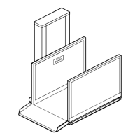
1) drawings following this text. To
# 21. The four sides of the Handilift
nt).
with eight (8) 10 1/4" (256 mm) x 1" (25 mm)
pan-head bolts that are provided with the angles that are factory attached to the tower.
See Figure # 21.
nsuring that
the platform stops:
xed ramp in a non-pitted application
support plate. See Figure # 21, SE Floor Plate.
This floor plate MUST be
s
Refer to the "General Arrangement" semi-enclosure
assist in identifying enclosure panels, refer to Figure
semi-enclosure have been identified as A, B, C and D, regardless of the hand of the unit.
(Specific drawings detailing your particular installation may have been forwarded with the
enclosure shipme
) Attach the two tower side panels, A1 and A2
2
3) Raise the platform to the top landing. Set the down limit switch assembly, e
a) at a position 1/4" (6 mm) above the lower landing in a pitted application
b) at a position 1/4" (6 mm) above the fi
4) a) In a ramped application, panel C1 and lower landing gate (B1) share a common
inserted into the bottom of the frame tubes of these two panels BEFORE
positioning them.
When installed, the panel assembly can be located and
mounted to the tower return wall, using the hardware provided. The floor plate ha
mounting holes inside the hoistway for fastening this assembly to the floor.