28
LECTRICAL CONNECTIONS
A sch
SCHE ectrical
conne ent the schematics package.
When iring
r any specified options; such as, battery, alarm, and/or platform gates. Field wiring would be required
the case of connecting landing gates to the controller.
) a) Electrical power may be supplied with a standard 115V plug for residential use but
must be on a properly rated, dedicated slow blow/motor start circuit.
b) Electrical power may also be connected by bringing the power supply in from the
fused disconnect to the controller through the 1/2" conduit hole provided at the
bottom of the tower.
) Confirm that the electrical source is 115 Volt, Single Phase, 60 Cycle, 15 Amp. minimum
for 550 lbs. (250 kg) capacity or 20 Amp. for optional 750 lbs. (341 kg) capacity. In
Europe, 220 Volt, Single Phase, 50 Cycle, 10 Amp.
OTOR/CONTROLLERS
NOTE
E
ematics package is included with this manual (See APPENDIX “A” - ELECTRICAL
MATICS). The following text is composed of general notes and guidelines to assist the el
ctions phase of your installation, and is intended to complem
MAIN POWER SUPPLY
shipped, the Concord Handilift is pre-wired and tested at the factory. Pre-wiring includes w
fo
in
1
2
M
Always raise and remove the service panel carefully as it is heavy and somewhat cumbersome
and may be scratched and cause scratches to the finish of the lift tower and/or cab during
removal.
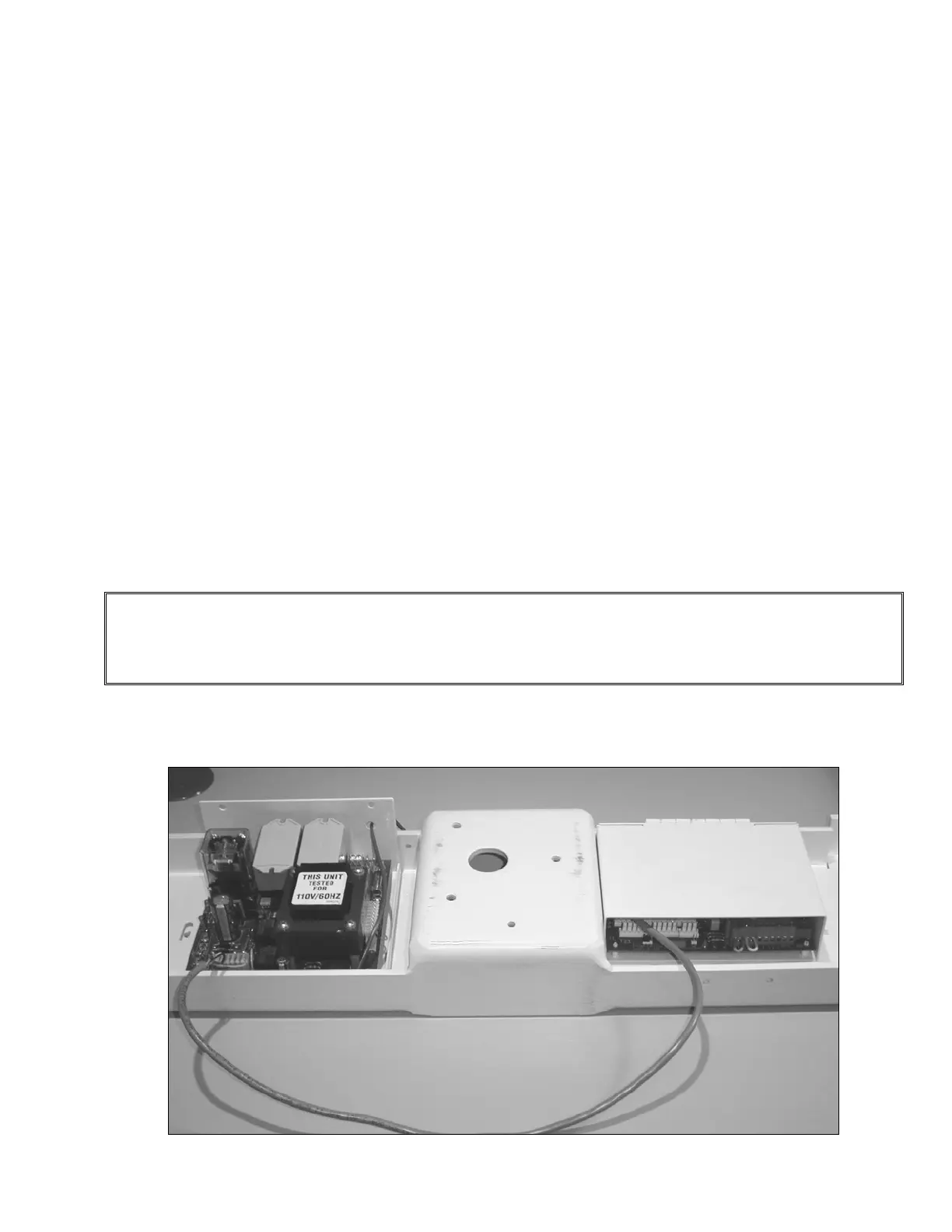
1) The controllers are attached to the underside of the crosshead support channel at the top
of the tower. See Figure # 17.
Figure # 17 Controller Assemblies