29
t and hinge the power control board downwards (left controller).
) To remove the cover, remove the three (3) #8-32 screws being careful not to damage the
wiring contained inside. There is additional wiring to allow the cover to be moved far
enough out of the way for easy access to the controller. Note: The motor thermal
overload (reset) is located on the outside of the cover.
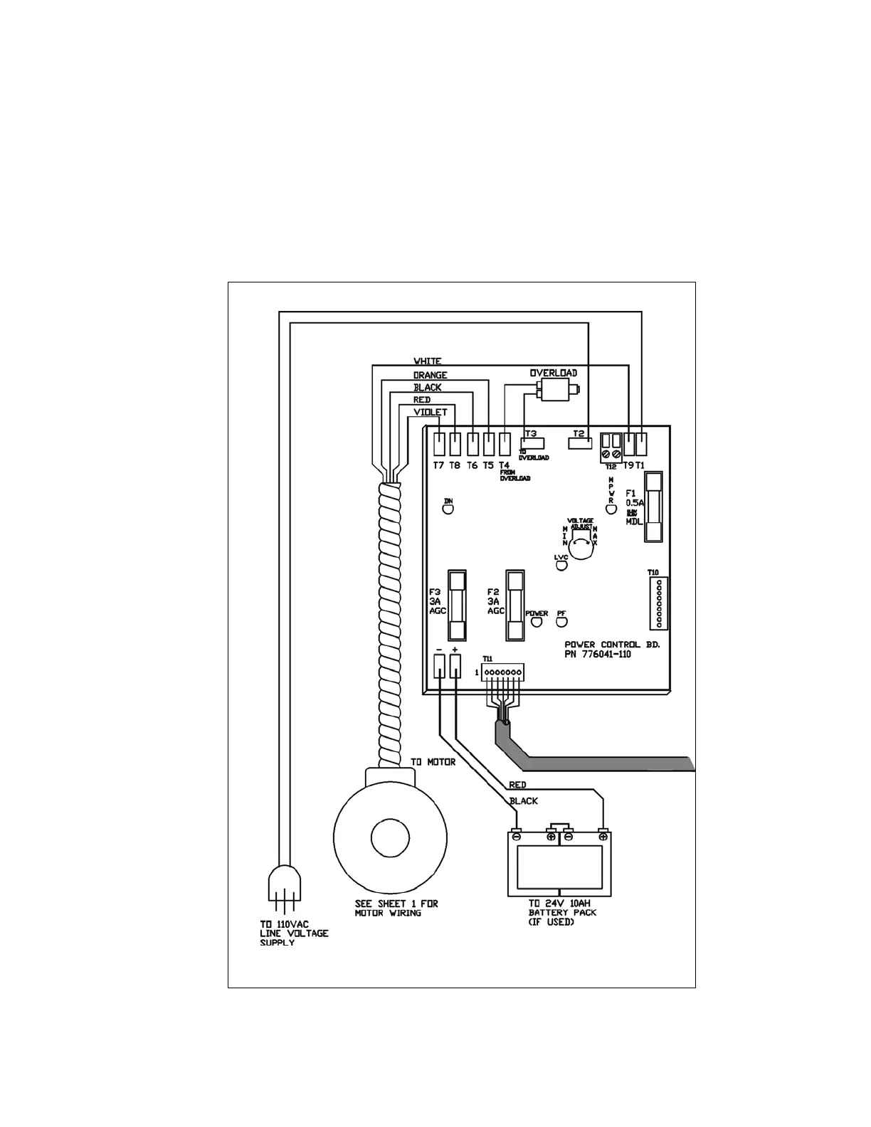
4) Connect the power supply to connection “T2” (black wire, smooth) and “T1” (white wire,
ribbed) on the left controller. See Figure # 18. (Use only a motor starting-type fuse in the
fused disconnect). The disconnect should be lockable and mounted near the unit.
2) Remove the retainer nu
3
rol Board Figure # 18 Power Cont