23
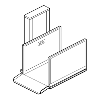
Figure # 13 Landing Door/Gate
(6 mm) drive pins or #12 wood screws to
anchor the sill, depending on site conditions.
Anchor the hinge and latch post of the
Final mechanical installation
INSTALLATION OF CALL/SEND STATIONS (OPTIONAL)
To connect the Call/Send Rocker Switches, review Electrical Schematic Sheets 8.0 - 8.9 in the Appendix
A” section of this manual. Note that there are three (3) connections on each rocker switch. The center
ween the “UP” and “DOWN” connections. To connect to the main
atic Sheet 7.0 in the Appendix “A”
To add a key switch, remove the jumper across the keyswitch pins on the screw terminals and add the
ANDING DOORS/GATES (OPTIONAL)
Instal
site requirements.) Normally, the gate/door
) Set the distance to the platform using a 1/2"
3) set and
anchor the sill plate. Use either 1/4"
4)
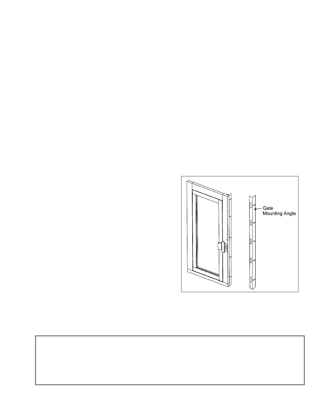
gate/door to the wall or support, using the mounting angles. One-quarter (1/4" or 6 mm)
holes have been drilled in the side of each gate/door post to assist in fastening. Drill
additional h
“
connection is the “common” bet
ontroller, review the simulated control legend on Electrical Schemc
section of this manual. Note that at the bottom of the R/H board, there are two terminal strip
connections marked appropriately, “TO LOWER LANDING” and “TO UPPER LANDING”. The
terminal strips are each marked “A,B,C,D,E,F,G,J,K,L”.
key where the jumper was.
L
Landing Door/Gate
l the upper landing gate/door, using the following procedure:
1) With the Handilift at the landing, place the
gate/door in front of the platform. (Refer to
layout drawings and position it, according to
is centered on the platform when at a
landing. See Figure # 13.
2
to 3/4" (13 mm to 19 mm) piece of plywood
and clamp the gate/door to the platform,
depending on the running clearance
desired.
Holding the gate/door in position,
oles, if necessary.
NOTE
The wall (support) is generally furnished by the contractor/owner. This wall or support must be in place
before setting the gate/door to facilitate the installation. Pay particular attention to constructing a
perfectly square assembly before final fastening of the gate/door. The gate/door is unstable until
fastened to the wall (support) and may easily be installed "out-of-square". Temporarily fasten the
gate/door. Check that the gate/door opens and closes properly. Check that the gate/door and frame
align squarely to each other when closed.