21
LIMIT SWITCH ASSEMBLY
1) ent bolts and extend the switch assembly as high as needed
2) Re-a sing
the tw
) Use tie-wraps to fasten the excess wire to the slotted bracket and keep the wire clear of
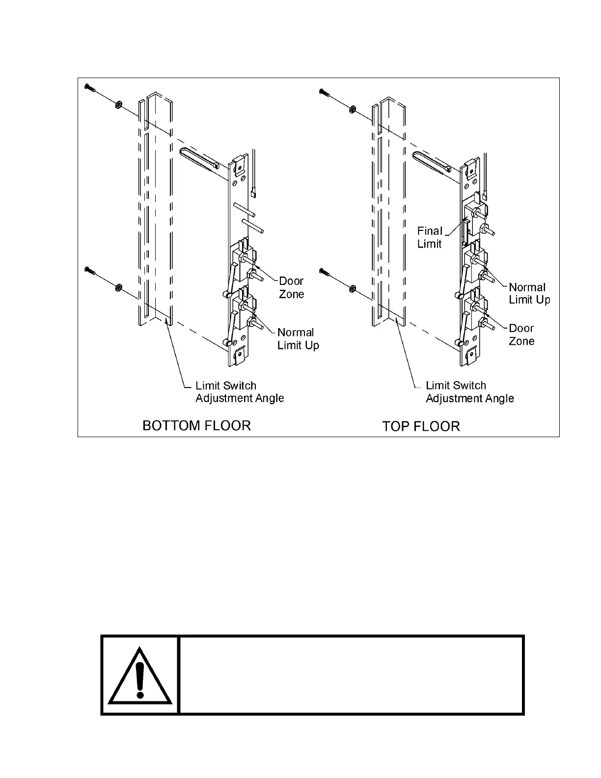
any moving parts. Refer to Figure # 12 for the functions of the limit switch assemblies.
Remove the two (2) attachm
Figure # 12 Limit Switch Assemblies
to suit the site travel.
ttach the upper limit switch assembly to the slotted adjustment angle bracket, u
o (2) bolts previously removed.
3
TEST RUN THE LIFT
TO AVOID PERSONAL INJURY, NEVER STAND
DIRECTLY UNDER THE CAB OR INSIDE THE HOISTWAY
DURING TESTING. PRACTICE SAFETY FIRST.